I want to use a smartphone as the audio source with my music going to the amp. It works, but the sound is really low unless I turn up the volume all the way up on my smartphone.
I bought the 2.1 amp below and the sound is a little low even with a 19 volt dc psu. I was wondering if there is a resistor that I can change or add a variable pot to increase the input gain.
The amplifier that I bought is here:- TPA3116D2 2x 50W +100W 2.1 Channel Digital Subwoofer Power Amplifier Board | eBay
Thanks
In order to select the amplifier gain setting, the designer must determine the maximum power target and the speaker impedance.
Once these parameters have been determined, calculate the required output voltage swing which delivers the maximum output power. Choose the lowest analog gain setting that corresponds to produce an output voltage swing greater than
the required output swing for maximum power.
Pin 8 is the gain control.
Thank you all for the replies.
Turn the phone volume all the way up and use the pot on the amp to control the listening level. I did this and the sound volume is good, but I feel that it’s still a little low as I still have to turn the pot on the amp all the way up as well as the volume control on the smartphone.
I think that I will have to read the schematic suggested and alter the resistor at pin 8. I just have to figure out what resistor for the pots, as I may need to put one on the subwoofer an well as the stereo channels.
I’m new to this, so I was wondering how should the pot be oriented. I know one end should go to pin 8 and the other to the ground, but what about the this pin on the pot?
Attachments
No............I’m new to this, so I was wondering how should the pot be oriented. I know one end should go to pin 8 and the other to the ground, but what about the this pin on the pot?
Your volume potentiometer needs a Signal Input from the Source and sends a Signal Output to a Receiver.
The Signal Input from the Source is a two wire connection. You must use two wires from Source to vol pot. Connect the Signal Flow wire to an outer pin of the three. Connect the Signal Return wire to the other outer pin ("bottom" pin). Make sure the two wires and the terminations are close coupled all along the route. You can use coaxial cable to maintain this close coupling, the core is the signal flow wire and the screen is the signal return wire. If you use coax then keep the exposed core very short, keep the screen intact to as close to the signal connection as you can.
At the output the Signal flow wire is connected to the middle (wiper) pin and the signal return is connected to the "bottom" pin.
Again maintain close coupling of the signal Flow and Signal Return wires all along the route of the two wire cable, including the terminations.
You can identify the "bottom" pin by turning the vol pot all the way down to minimum and then using a continuity meter/ohm-meter to measure from wiper to outer pin. The outer pin that reads near zero ohms is the "bottom" pin. This pin will now have TWO wires. The signal RETURN wire going back to the Source and the Signal RETURN wire coming back from the Receiver.
On both sides of the vol pot you have two wires to transfer the signal. Both wires are SIGNAL wires. None are ground.
If you have a metal can around your vol pot or a metal shaft then these two metal parts should be electrically connected to chassis. Some would refer to these connections as grounding.
Last edited:
I’m new to this, so I was wondering how should the pot be oriented. I know one end should go to pin 8 and the other to the ground, but what about the this pin on the pot?
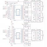
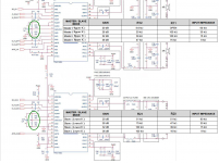
No. You will not install a pot there. See the attachment.
You have to access the circled resistors and change their values to obtain a higher gain.
With the values shown in the schematic you provided, the gain is 26dB.
You can go to 32dB or to 36dB
George
Attachments
No. You will not install a pot there. See the attachment.
You have to access the circled resistors and change their values to obtain a higher gain.
With the values shown in the schematic you provided, the gain is 26dB.
You can go to 32dB or to 36dB
George
Thank you all for the replies.
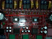
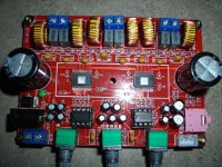
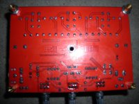
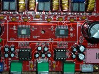
I think that if I can just change the resistors as mentioned it will work. The only thing is that it looks like it was soldered my machinery as the resistors are really small, and I don’t know if I can work on it, but I’m willing to give it a try.
I’m also enclosing some photos that I hope would help as suggested by “irribeo”.
Thanks.
Attachments
Gainsetting indeed is standard (26dB) datasheet, stereo left right is master, bass is slave here. Standard datasheet r25/c40 values do not function, and resistor r25 is datasheet value, so likely c40 is too. Master is supposed to send signal to slave so that slave's switchingfrequency is equal to master's. Here slave does not receive signal from master, which most times means slave will switch at ~100kHz. Some report noise issues and distortion issues, maybe slave isn't stable at ~100kHz, I don't know, minimum switchingfrequency for the chip is supposed to be 400kHz, here master is operating at that frequency. For bassfrequencies it won't be a direct quality problem, however you might have some indirect problems, because the outputfilter hardly attenuates the 100kHz switchingresidu, there will be a very strong high frequency (100kHz +) noise signal on bass output. Better not connect a multiway speaker (with tweeter) to bass output.
Intended correct values for r25/c40 are 4k7/47pF, you could change those too or if you find it easier, remove r25 and set both amplifiers as masters, use identical resistor pairs for the gain/master/slavesetting r18/r19 , r27/r28
Intended correct values for r25/c40 are 4k7/47pF, you could change those too or if you find it easier, remove r25 and set both amplifiers as masters, use identical resistor pairs for the gain/master/slavesetting r18/r19 , r27/r28
Simple mental estimations say that a 19V fed amplifier can put out maximum 6V RMS or thereabouts.
So 26 dB gain (20X) requires 6000/20=300mV RMS out of your smartphone, which is on the edge or worse .
Raising amp gain to 36dB as mentioned above will lower requirement to around 100mV RMS, which practically *any* headphone out can supply.
So 26 dB gain (20X) requires 6000/20=300mV RMS out of your smartphone, which is on the edge or worse .
Raising amp gain to 36dB as mentioned above will lower requirement to around 100mV RMS, which practically *any* headphone out can supply.
Gainsetting indeed is standard (26dB) datasheet, stereo left right is master, bass is slave here. Standard datasheet r25/c40 values do not function, and resistor r25 is datasheet value, so likely c40 is too. Master is supposed to send signal to slave so that slave's switchingfrequency is equal to master's. Here slave does not receive signal from master, which most times means slave will switch at ~100kHz. Some report noise issues and distortion issues, maybe slave isn't stable at ~100kHz, I don't know, minimum switchingfrequency for the chip is supposed to be 400kHz, here master is operating at that frequency. For bassfrequencies it won't be a direct quality problem, however you might have some indirect problems, because the outputfilter hardly attenuates the 100kHz switchingresidu, there will be a very strong high frequency (100kHz +) noise signal on bass output. Better not connect a multiway speaker (with tweeter) to bass output.
Intended correct values for r25/c40 are 4k7/47pF, you could change those too or if you find it easier, remove r25 and set both amplifiers as masters, use identical resistor pairs for the gain/master/slavesetting r18/r19 , r27/r28
I'm new at this so I can use all the help provided. Can you be give me a little more detailed instructions for replacing the r18/19, r2/,r28? What should the values be for these resistors? Do I need to change c40 too? Also, you said to remove r25 and set both amplifiers as masters. How do I that?
The TI data schematic may not be the same for my board as I tried measuring the resistance the following resistors on my board and it didn't match the resistance on the data sheet.
Actual measurements taken from my board.
R20=15K
R11=5K
R12=19K
Thanks
Simple mental estimations say that a 19V fed amplifier can put out maximum 6V RMS or thereabouts.
So 26 dB gain (20X) requires 6000/20=300mV RMS out of your smartphone, which is on the edge or worse .
Raising amp gain to 36dB as mentioned above will lower requirement to around 100mV RMS, which practically *any* headphone out can supply.
That's what I really hope to accomplish. Hopefully I will be able to get it done.
If you are able to remove the tiny resistors without damaging them you could swap them, r27 with r19, r28 with r18, and end up with 36dB for left right and 36 (or 32) dB for bassoutput. Maybe 32dB for bassamp because datasheet gives 16k value for 36dB slave.
If you only remove c40 you have a slave amp folowing the masteramp, but highfrequency noise from master gets injected into slave. 47pF there filters some HF noise from master amp.
If you only remove c40 you have a slave amp folowing the masteramp, but highfrequency noise from master gets injected into slave. 47pF there filters some HF noise from master amp.
If you are able to remove the tiny resistors without damaging them you could swap them, r27 with r19, r28 with r18, and end up with 36dB for left right and 36 (or 32) dB for bassoutput. Maybe 32dB for bassamp because datasheet gives 16k value for 36dB slave.
If you only remove c40 you have a slave amp following the masteramp, but highfrequency noise from master gets injected into slave. 47pF there filters some HF noise from master amp.
Thank you for taking the time to decode and explain what needs to be done. I understand now what I need to do. I think that if I work slowly and carefully that I’ll be able to swap the resistors.
Replacing the C40 with a 470pF part that maybe a little tricky, as it’s located under the heatsink, so I may have to order a SMT Chip Capacitor.
Attachments
Do you have a DMM with Frequency option ? Or one that can measure capacitance ?
Without c40 bassamp works properly, with standard 1nF it doesn't, with your 470pF it is not likely to function properly. The zero you add is important.
No, I just have a basic analog multimeter. Also I made a typo I meant 47pF instead of 470pF.
Are you saying that I can just remove the c40 capacitor and the amp will work properly as a slave and master? I remember that you said I needed c40 to be 47pF to filter HF noise from master amp.
Yes without c40 the slave will follow master exactly. Yes the master synch output might inject some more HF noise into slave chip than with small value c40. You can never hear that, maybe a wireless connection or radio/tv reception or other electronics functioning in house will notice, but c40=1nF causing the slave not to receive synch signal seems more likely to cause all that. But I can only guess.
- Status
- This old topic is closed. If you want to reopen this topic, contact a moderator using the "Report Post" button.
- Home
- Amplifiers
- Chip Amps
- Help needed to increase the input gain on a TPA3116D2 amp