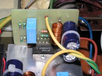
Hello everyone! I am really proud and happy to introduce my latest creation.
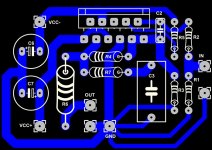
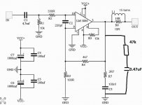
The famous Gainclone with LM3886, schematic is from the great Carlos.
Please note:
C1 was connected directly to the out of an Alps 20k pot.
L1 was made with 15 turns of 1mm wire on a 8mm diameter.
C4-C5 were welded directly in the PCB.
Snubber is only in the PSU because I haven't all the components.
Power Supply is from a 18v + 18v AC transformer.
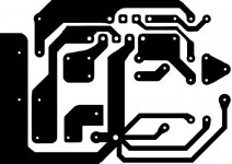
PCB was made by me with the Press'n'peel technique.
All designs are created by me, NO Eagle!!!
Actually the amp is connected with the Scythe Kro Craft and a CD Player.
This amp is really fantastic, NO noise, NO humm, NO hiss...nothing!!
I've connected even a headphones...fantastic!!
What impressed me most is the mute/soft start function. Very silent!
No noise when power up, no noise when shutdown!
I would like to thank Carlos for his great work.
The famous Gainclone with LM3886, schematic is from the great Carlos.
Please note:
C1 was connected directly to the out of an Alps 20k pot.
L1 was made with 15 turns of 1mm wire on a 8mm diameter.
C4-C5 were welded directly in the PCB.
Snubber is only in the PSU because I haven't all the components.
Power Supply is from a 18v + 18v AC transformer.
PCB was made by me with the Press'n'peel technique.
All designs are created by me, NO Eagle!!!
Actually the amp is connected with the Scythe Kro Craft and a CD Player.
This amp is really fantastic, NO noise, NO humm, NO hiss...nothing!!
I've connected even a headphones...fantastic!!
What impressed me most is the mute/soft start function. Very silent!
No noise when power up, no noise when shutdown!
I would like to thank Carlos for his great work.
Attachments
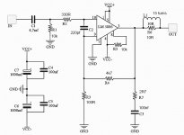
bad sch.
The +IN pin of lm3886 sees 330r+10k as the resistive load.
The -IN pin sees 100r||4k7 as the resistive load.
That will give the amp a big output offset. and it will drift a bit more as the temperatures vary.
Do not mix AC and DC coupling at the inputs.
gain is (4700/100)+1 = 48times (+33.6dB) that is quite high leaving the input sensitivity @ ~ 416mVac. You will probably have to turn your vol pot right down to get listenable stereo.
I would change the two input filters.
4u7F into 10k gives ~ 3.4Hz.
330r into 220pF gives ~ 2.2MHz
One has been set ~ 5times below audio, the other has been set ~110times above audio. A bit unbalanced. Make then both about 10times outside the audio band.
The unmute is set to instant on and instant off. What about adding the capacitor to delay mute/unmute?
What impressed me most is the mute/soft start function. Very silent!
No noise when power up, no noise when shutdown!
Doesn't matter how non ideal it might be, if its silent at power on and power off then it doesn't get any better than that.
It would be interesting to know what actual DC offset you have at the output as it is always interesting to compare real builds with theoretically ideal versions. I would have to agree with Andrew on this point though, it wouldn't normally be done that way, having unbalanced DC bias paths. Around 100mv offset would be as high as could be considered acceptable. Hopefully it is somewhat lower.
Silent is not good for audio reproduction.
That's a bit out of context Andrew. I think you know what was meant i.e. silent with regard to unwanted noises at power on/off.
I don't know how you have been so lucky. It certainly wasn't by design.
....design schematic? or PCB?
That is low, especially considering the quoted input bias currents from the data sheet. I would have said it would have been somewhere in the 90mv region tbh.
However")
Maybe I've made an error?
I've measured it with input shorted to ground...if I leave it open, I get more than 90mv, If I remember good...
bad sch.............
I don't know how you have been so lucky. It certainly wasn't by design.
....design schematic? or PCB?
This indicates that the DC blocking capacitor is not working.Maybe I've made an error?
I've measured it with input shorted to ground...if I leave it open, I get more than 90mv, If I remember good...
An AC coupled input does not change output offset when the input is shorted.
The output noise changes when the input is loaded down with a low value, or zero value resistance.
Maybe I've made an error?
I've measured it with input shorted to ground...if I leave it open, I get more than 90mv, If I remember good...
Well the input is AC coupled and so shorting the input will not affect the DC conditions. What it will do though is alter any noise/hash that may be present and even a small amount can 'confuse' a DVM. Ideally a scope should be used to check the output is clean.
A simple low pass filter consisting of a 47k and a 0.47uf film cap (values not critical) in series and connected across the output (the same as your R7 and C3) will allow a DVM to give a true DC reading. Just measure the voltage across the cap.
mmmmhhh... I never studied electronics....can you write a schema?
Hi !! After ONE yeartoday I've made measurements with Mooly's advice.
I'm really confused.. and I think AndrewT will be very happy and sad!!!!!
One channel have -10mv of output DC
One channel have 50mv of output DC.
I don't know:
1) why this difference form two channels
2) why 50mv....
And so...I hope you can give me all advice I need to modify all, but
remember, amplifier is really dead-silent, nothing on the speakers when
power on and power off.
Maybe it's important for you: I made measurements with amplifiers really cold.
Thank you again!!
- Status
- This old topic is closed. If you want to reopen this topic, contact a moderator using the "Report Post" button.
- Home
- Amplifiers
- Chip Amps
- My Gainclone (by Carlos)