hello again,
I get lots of interferences into some TDA7293 monblocks, its only 100mm of cable. I found in the web, one could use ferrite beads. But that sounds more like they should be used in the emitter, not in the receiver, as signals would be induced into them? I tried today, and alas, it only makes it worse.
Shielded or twisted cables does not help either.
I could try this next
Church Sound: Church Sound: Preventing Hum And Radio Frequency Interference (RFI) In A System - Pro Sound Web
or better lower the input impedence, as theere is a crossover in front of the TDAs and there are opamps into a 22k ohm poti, so their impedence is pretty low. I tink a few ohm for the OPA134. Or even boost the signal at the exit of the opamp.
cheers,
Case
Last edited:
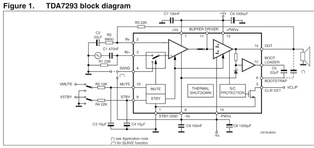
Okay, you've put the schematic in another post which is weird.
The schematics have no RF interferance parts.
The amp needs to be in a grounded steel case. Not stainless steel, ferrous.
If you've built these you are in luck. You can modifiy with the standard treatment. If you've bought them, and there is no room in there, scrap them and buy real PA equipment from a major vendor, Crown, QSC, Peavey, Yamaha come to mind. Or you can yank the TDA7293 board and put in a real grounded steel enclosure big enough to put the extra parts in. Don't forget the fuses or circuit breakers on input. I like hinge top steel recipe files as enclosure, with the board on the hinged top. Use a Stanley carbide hacksaw to cut any square holes or triangle holes (IEC socket) required. Connect the safety ground to the steel case with a 16 ga or larger wire, using a washer with biting tangs to break the oxide, and a real machine screw and nut, not a sheet metal screw. You can salvage these from any appliance that has an external steel part. I also buy stainless steel internal tooth washers by the box of 50 from an industrial supply for my car body grounds.
At the output of each device needs to be a zobel network. This is a 1000 ohm 3 watt resistor, series a .047 or .1 uf capacitor, between speaker hot and return. My dynaco ST120 amp puts them right on the back of the banana jacks.
Furthermore in the speaker line needs to be a RF buck coil. This is something like 10 turns of wire, 22 to 16 ga, wrapped around a 3/8" dowel or a AA battery. Remove the battery. parallel that is a 3 to 10 ohm 5 watt resistor. My amp has this mounted near the output jack, and away from the amplifier inputs. If you have dead PCAT power supplies or televisions, these are full of suitable coils in the switcher supply.
On the input of the amp, 33 to 100 pf ceramic cap goes between the hot and return of the input jack. When my cable went up from 6' to 12' due to a furniture move, I had to increase my input capacitor to 68 pf from 33 to remove the RF from a radio station 4 miles away.
If you have op amp inputs from dynamic mikes, with XLR or stereo phone plug inputs, you can use a differential input. Wire the op amp plus and minus inputs to the XLR 2 & 3 or phone plug tip and first ring, hot to 2 or tip. The circuit of the op amp should be like that used in a pro amp like the Peavey PV-1.3k schematic on eserviceinfo.com or the PV-4C on elektrotanya.com. Then the cable used should be twisted pair with the mike hot and return being the two twisted input wires.
I see no Hash filter in your schematic, either. PCAT power supplies and televisions now have a board with two toroid inductors in series with the AC hots coming into the switcher supply. This can be salvaged from dead ones. If your 24 comes from a wall plug, you can put these in series with the + & - DC coming into your enclosure. this keeps pops from refrigerator or AC motor shutoff getting into the sound. If there is an E-frame transformer near the input of the power into the enclosure, this can be skipped. At the output of the e-frame transformer, the input of the bridge rectifier, put a .01 uf 1000 v disk cap.
Ishida weighers use ferrite beads on the AC lines inputs instead of toroids chokes, but I don't know of a source to buy them.
IN your enclosure, put the input and output connectors away from each other. Make the input wires and speaker wires non-parallel. The input should be twisted pair.
These are all standard treatments to prevent RF interference. If you've disassembled a PA amp like a PV-4C or PV-1.3k you'll find similar components.
Best of luck.
Last edited:
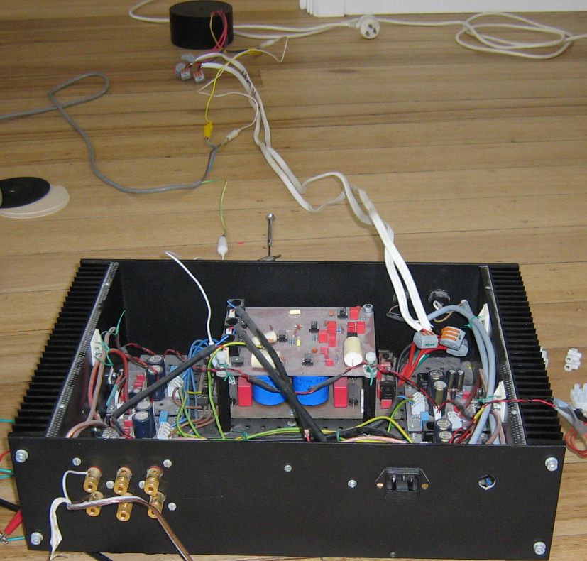
Its an amp that I am building. Its only 4 inch cable between the crossover and the monoblock, and that is already causing problems
An externally hosted image should be here but it was not working when we last tested it.
I pulled everything out, put the transformer 1m.3 feet away, still humming. Only becomes quiet, when I run it of a lab power supply. The other post, if I make band passes, at least it not amplifies everything.
Ferrite beads at element14 former Farnell or RS components.
Ferrite beads at element14 former Farnell or RS components.
Last edited:
Uh, yeah. PEavey puts a copper shell around their transformers, and puts it behind a grounded steel wall inside the enclosure, effectively making the transformer in a separate enclosure. The PV-1.3k has the transformer 8" away from the input op amp. The IEC connector and Circuit Breaker are in its own little steel box 14" away from the input board. The CS800s has its own steel box for the AC and switcher parts stuffed in the case away from everything else.
Dynaco has separate steel enclosure for the transformer switch filter and indicator light parts inside their PAS2 preamp, which doesn't hum.
I suggest your enclosure is too small. Get the transformers out entirely and put them in your own separate enclosure, with the DC running over to the amplifier part. beads or toroids can be ueed in this enclosure near the input jack to keep the RF and hash out of it.
You may be able to stack your boards to get them away from the transformer box inside your case. This makes it difficult to debug. Peavey handled this by making the driver boards swappable inside the PV-1.3k so you can put whichever one is blown up on top.
I make standoffs out of 1/4" nylon air tubing. I use 1" to 3" #6-32 screws with elastic stop nuts to fasten things. I use elastic stop nuts so they don't come loose. In OZ you would use 3 mm or 4mm hardware I imagine.
I finally killed the hum in my disco mixer with a double pi filter. There is a wall transformer totally separated from the mixer. There is a 1 ohm resistor in both Dc lines coming in, then a 1000 uf cap parallel a .1 uf cap, then the toroid hash filters, then a 1000 uf cap parallel a .1 uf cap, then the zener voltage regulators series power control resistors, then another 1000 uf cap, then off to the input boards. The op amps have their own .1 uf filter caps close by.
I also separated the ring of the RCA input & output jacks from case ground with o-rings. Making analog ground and safety ground separate entities, connected only by a resistor.
Last edited:
noise is still there in this setup, no mains going into the box. Its quiet, when I shorten out the monoblocks inputs to ground with a jumper. Its also quiet, when I take that short cable between the xover and the monoblocks off. Xover is only connected to the star ground. Drives me insane. Maybe I go for switch mode supplies instead. Its only drawing 14W or so. The boards are on metal standoffs, M3. Should switch tem for plastic.
Don't see a separate grounded steel enclosure for the transformer. Don't see the Hash filter coming in the amp. Don't see the zobel network. Dont see the coil on the speaker output. Don't see twisted pair input wiring. Don't see a pi filter.
Plenty of remedies to do yet. The boring part of the project is the part that gets rid of RF & hum. My Herald RA-88A was a hummy packaging disaster, the reason I got it for $15 with absolutely new slider pots. they put the transformer & power switch right next to the 50X gain mag phono circuit, then "killed" the hum with a 330 ohm resistor in the DC line right after the single cap hum filter. Hum was down maybe 50 db, not good enough. I've got it down maybe 80 db now, just by repackaging and more pi filtering. Circuit designer double plus for cost effectiveness, the packaging guy was an idiot.
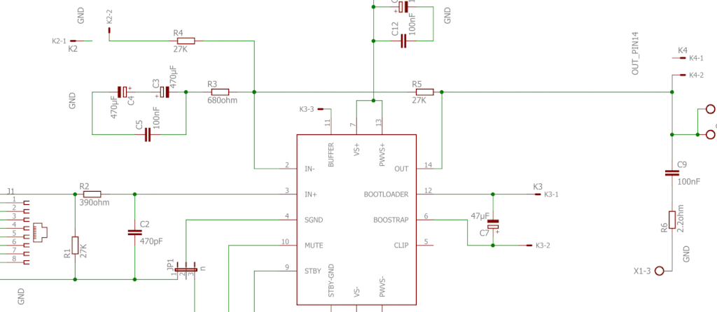
Oh, for anybody interested, the board schematics are in this thread: http://www.diyaudio.com/forums/solid-state/303210-bandpass-tda7293-monoblocks.html
Plenty of remedies to do yet. The boring part of the project is the part that gets rid of RF & hum. My Herald RA-88A was a hummy packaging disaster, the reason I got it for $15 with absolutely new slider pots. they put the transformer & power switch right next to the 50X gain mag phono circuit, then "killed" the hum with a 330 ohm resistor in the DC line right after the single cap hum filter. Hum was down maybe 50 db, not good enough. I've got it down maybe 80 db now, just by repackaging and more pi filtering. Circuit designer double plus for cost effectiveness, the packaging guy was an idiot.
Oh, for anybody interested, the board schematics are in this thread: http://www.diyaudio.com/forums/solid-state/303210-bandpass-tda7293-monoblocks.html
Last edited:
Just read your other post - it is not clear whether you are doing bandpass filtering with opamps before the power amps, or whether you are trying to do the bandpass filtering as part of the poweramp's feedback loop. If you are doing the latter - don't do that.
If you are doing the former, make sure all of the signal grounds only connect to the power ground at ONE point, and isolate the two with a 10 ohm resistor bypassed by a 100nF capacitor. Make sure you are using proper star earthing techniques too.
If you are doing the former, make sure all of the signal grounds only connect to the power ground at ONE point, and isolate the two with a 10 ohm resistor bypassed by a 100nF capacitor. Make sure you are using proper star earthing techniques too.
its star ground, but that did not help. The small transformers are not connected. Fridge is pretty new and rain water pump is far away, runs via pressure sensor.
Its all quiet when its powered through a lab power supply. Since I got the ferrites now, may as well put them around the wires of the transformers. In the olden days computer mice had them, but that was to get rid of emissions I guess.
Yes, there is an opamp active filter before the TDAs, but I was thinking, if I narrow the range down again at the TDAs, they would amplify less unwanted noise. That filter,I could put a booster in at the output, then lower the impedance at the TDA input, this would get rid of some interference.
Last edited:
The key is to stop the noise being picked up and being amplified in the first place! Power opamps like chip amps tend to do nasty things if you try and use complicated bandpass in their feedback networks. Its not really what theyre designed for.
When you say, interference, what does it sound like ?
What happens with just the power amps on their own, without the preceeding opamp stages?
What happens when you hook the opamp stages to another amplifier?
When you say, interference, what does it sound like ?
What happens with just the power amps on their own, without the preceeding opamp stages?
What happens when you hook the opamp stages to another amplifier?
its star ground, but that did not help. The small transformers are not connected. Fridge is pretty new and rain water pump is far away, runs via pressure sensor.
Its all quiet when its powered through a lab power supply. Since I got the ferrites now, may as well put them around the wires of the transformers. In the olden days computer mice had them, but that was to get rid of emissions I guess.
Yes, there is an opamp active filter before the TDAs, but I was thinking, if I narrow the range down again at the TDAs, they would amplify less unwanted noise. That filter,I could put a booster in at the output, then lower the impedance at the TDA input, this would get rid of some interference.
Your intuition was right IMHO
Your transformer is the problem, i've recently buyed and encapsulated talema toroidal transformer and encountered a vibration issue (i've mounted it on silent blocs).
There is no safe choice... i've buyed many toroidal and EI transformers (always encapsulated) and some of them are humming and others are totally silent (not always the most expensive
") )
)Be careful if you choose a switching PSU, some of them (a lot) are noisy in the HF

Last edited:
I isolated everything. The opamp filter network is not connected to anything, only to the star ground. The toroid transformer sits on te floor 1m away. the only thing going ito the amp is 2x22V AC from the toroid. If I leave the 10cm long cable on the TDA amp, its buzzing, if I take it of, its gone. If I put a ferrite bead on, the buzzing gets worse. Its more like a sawtooth noise, not a pure 50Hz hum. It keeps going, even if I power off the toroid. There are 2x10000uF per rail, then 2x2uF and 2x 1.5uF. And each TDA has another 1uF. Takes a while to discharge. Has to be the cable picking up noise. If I shorten the TDAs input to 0V its completely quiet, if I leave it open, no cable to it, there is minimum hiss/white noise. But have to stick my ear into the speaker to hear it.
There is another 3V DC coming in from a lab supply, for the mute. Can consider that clean.
Off to the post office, pick up a parcel. Hope its the Gauss meter from ebay....
The original schematic from ST is very lean, mine I found from a DIY kit, has a few more filters in it.
There is another 3V DC coming in from a lab supply, for the mute. Can consider that clean.
Off to the post office, pick up a parcel. Hope its the Gauss meter from ebay....
The original schematic from ST is very lean, mine I found from a DIY kit, has a few more filters in it.
Last edited:
Put the rectifier & filter caps for the mains & op amp supplies in the transformer enclosure. Which you haven't bought yet. Stop at a charity resale shop on the way home & see if they have a steel box you can use for the power supply. - Or look at the curb on garbage day. I've found 8.5"x11"x11" file cabinets there, full of grandma's old utility receipts (trash). Old steel room heater boxes would work and also have a power cord, strain relief, fuse, and switch.
Of course I'm retired and spend my days riding a bike on errands, plenty of time to look around and stop in to not buy things if they don't have them. Employed people, I sympathize with the demands of work.
Of course I'm retired and spend my days riding a bike on errands, plenty of time to look around and stop in to not buy things if they don't have them. Employed people, I sympathize with the demands of work.
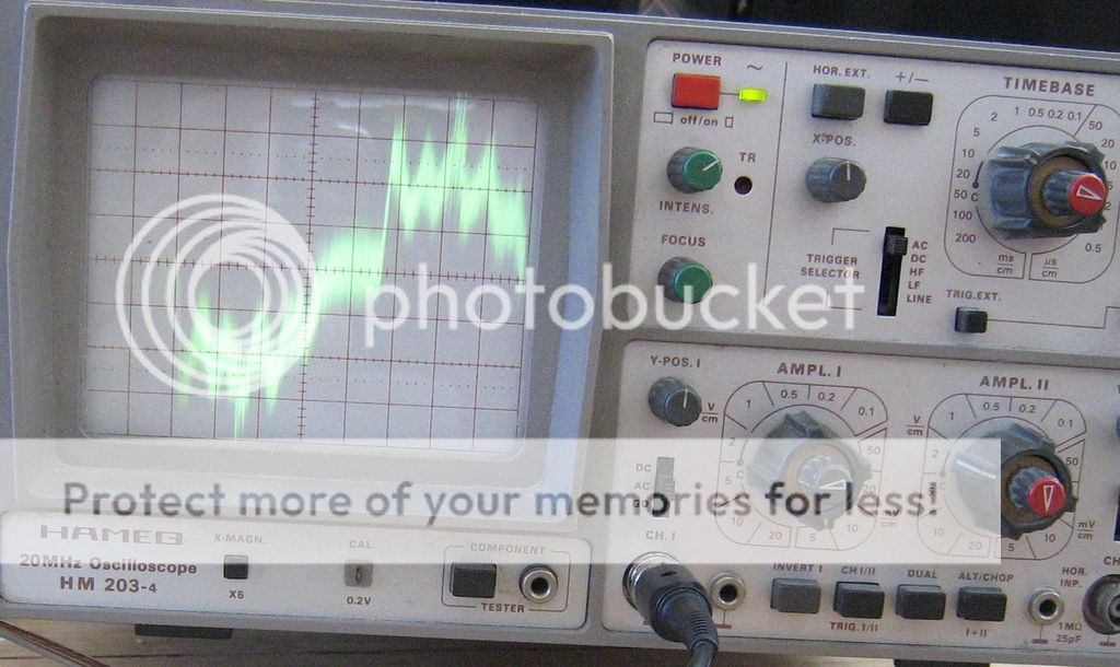
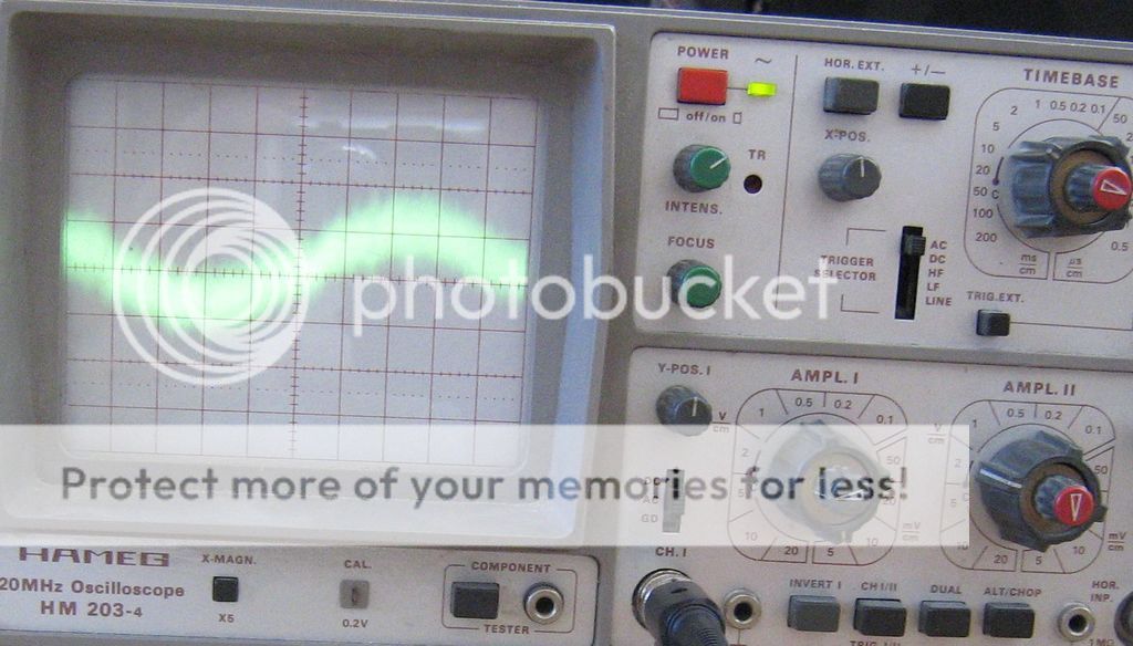
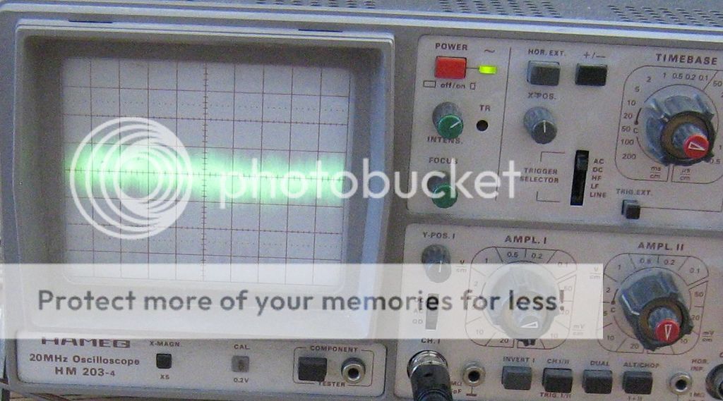
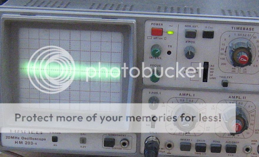
Oh, wow, 1.0 Vpp high frequency hash even with inputs shorted. If I read the amp 1 vertical knob right and you're using an x10 probe. That is pretty bad.
You might turn the time per div down and fiddle with the sync to see if you can get the bottom waveform to resolve to an oscillation. At what frequency? Or what period (1/frequency)?
You might turn the time per div down and fiddle with the sync to see if you can get the bottom waveform to resolve to an oscillation. At what frequency? Or what period (1/frequency)?
Last edited:
You can stuff the transformer in the case if you build a steel bulkhead around it. I cut sheetmetal with an 11 amp angle grinder with a 4.5" wheel (use safety glasses) and a vise. you can bend the screw flanges by chucking it in the vise and hammering the edge flat to 90 deg.
recommend the breaker, fuse, power switch, rectifier, intitial filter caps be behind the steel wall. use stainless star washers to ensure the wall is grounded to the case.
I'm building an IC amp today, LM1875. I have e-frame transformer & rectifier in one end of a 19" relay rack chassis 5" deep, amp board in the other end. We'll see if I have the hum problem and have to install a bulkhead this weekend. Input jacks are in used holes in the transformer end; which is starting to look like a bad plan. Chassis was originally a DC continuity tester for oil exploration geophone cables.
Last edited:
- Status
- This old topic is closed. If you want to reopen this topic, contact a moderator using the "Report Post" button.
- Home
- Amplifiers
- Chip Amps
- how to get rid of interferences-TDA7293