hello everybody, this is my first post here.
I am playing with electronics as a hobby, played with digital (arduino stuff and such), and lately wanted to try diy audio stuff...i have put my hands on a little Chinese 30w portable karaoke box, with line-in input and mic input.
It was dead (does not turns on) so i ripped it apart (i love ripping things apart).
The parts i found inside are TDA7379 chip powering big 30w 4Ohm speaker + small twitter speaker connected in parallel. That's pretty puzzled me since TDA7379 can power up-to 4 speakers, while here was only single speaker.
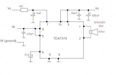
Anyway, i created a simple sample circuit, according to TDA7379 datasheet .
I connected it in Bridge mode (as in datasheet), while using only single input (left) and single output. I plan to feed the input with mixed L+R signal from line input.
I also put an audio pot between the line-in and amp input, to control the volume. The power is received from a 12v/2A wall-brick
In general this thing works and is pretty loud, however i got some strange noise which i cant seem to eliminate. Noise coming out of the speaker even if nothing connected. However if i touch chip heatsink, or metal part of the pot, much of noise goes away (still stays a little at a very acceptable level). So it seems like grounding issue, however I checked all grounds and they seem ok - i mean connected together.
Please help me to troubleshoot this.
Thanks in advance,
smarg
I am playing with electronics as a hobby, played with digital (arduino stuff and such), and lately wanted to try diy audio stuff...i have put my hands on a little Chinese 30w portable karaoke box, with line-in input and mic input.
It was dead (does not turns on) so i ripped it apart (i love ripping things apart).
The parts i found inside are TDA7379 chip powering big 30w 4Ohm speaker + small twitter speaker connected in parallel. That's pretty puzzled me since TDA7379 can power up-to 4 speakers, while here was only single speaker.
Anyway, i created a simple sample circuit, according to TDA7379 datasheet .
I connected it in Bridge mode (as in datasheet), while using only single input (left) and single output. I plan to feed the input with mixed L+R signal from line input.
I also put an audio pot between the line-in and amp input, to control the volume. The power is received from a 12v/2A wall-brick
In general this thing works and is pretty loud, however i got some strange noise which i cant seem to eliminate. Noise coming out of the speaker even if nothing connected. However if i touch chip heatsink, or metal part of the pot, much of noise goes away (still stays a little at a very acceptable level). So it seems like grounding issue, however I checked all grounds and they seem ok - i mean connected together.
Please help me to troubleshoot this.
Thanks in advance,
smarg
here is a link to sample schematics from the datasheet
again, i am using only left input and left output
An externally hosted image should be here but it was not working when we last tested it.
again, i am using only left input and left output
Last edited:
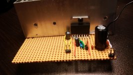
here is the picture...its not the state of the art work...just a poc ")
from right to left:
1) on a right side there is a connector for power, with filtering capacitors. the black wire is ground from audio pot (currently disconnected)
2) next in the middle is the input connector. there is also a 470 pf decoupling capacitor there, that is I believe is supposed to filter out inaudible high-frequencies? i am not sure if needed or not...have seen it in some schematics.
3) to the left of the input connector is chip stand-by components, according to schematics
4) next on the left side is a speaker connector, and further, closer to heatsink is capacitor connected to pin 6 of the chip
if i connect this as is (with speaker connected off course) - the amp is dead silent. but as long as i connect any jumper wire to amp input (i need it for now since the audio input is located on a separate breadboard for experimenting), it starts to produce noise, which is greatly reduced if i touch heatsink or basically any ground point...
Attachments
you can try to connect the metal tab/heatsink to power ground , i don't remember the internals of this chip and how is the metal tab connected.
if the noise goes away then its a good hint. probably you would have to wire the metal housing of the pot to gnd too.
and will see if it does anything at all.
if the noise goes away then its a good hint. probably you would have to wire the metal housing of the pot to gnd too.
and will see if it does anything at all.
Arty, i tried doing what you propose, it does not make any difference. the noise only goes away (almost) if i touch it - i.e. ground it to earth...however the original product had only 2 wires connection, without earth..so i believe it worked without noise and without requiring earth connection...
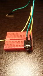
wwenze, ok i will try to draw a schematics, its pretty the same as in my second post here, just single channel - since it is mono.... the ground wire of the audio input is connected to the ground (power supply ground)
when the audio input is disconnected from the amp input (the middle connector in the picture), the amp is dead silent. however with short jumper wire connected it already produce that noise
when the audio input is disconnected from the amp input (the middle connector in the picture), the amp is dead silent. however with short jumper wire connected it already produce that noise
It is good. Add a series resistor of 2.2 Kiloohms for a defined lowpass.2) next in the middle is the input connector. there is also a 470 pf decoupling capacitor there, that is I believe is supposed to filter out inaudible high-frequencies? i am not sure if needed or not...have seen it in some schematics.
Use shielded cable. For you know, if source (the device we connect to line-in, and the volume potentiometer) impedance is hi, an open cable following the source works as a capacitor to other devices such as the power supply, picking up noise.if i connect this as is (with speaker connected off course) - the amp is dead silent. but as long as i connect any jumper wire to amp input (i need it for now since the audio input is located on a separate breadboard for experimenting), it starts to produce noise, which is greatly reduced if i touch heatsink or basically any ground point...
Arty, the power supply is simply a wall-brick providing 12VDC 2A output. i am not sure about 470nf cap to ground too...i have seen it on some schematics...my understanding it serves as low pass filter, to cut very high frequencies to amplifier, but i may be wrong.i will try to ground the second input channel and see what happens....i am not sure it is related, since it is dead silent when input cable is disconnected, but the moment i connect input cable to the first channel the noise starts....
It is good. Add a series resistor of 2.2 Kiloohms for a defined lowpass.
great, so my understanding is correct...so, why 2.2 K? why not putting a resistor of 15K? we want to cut frequencies above 20Kh...
Use shielded cable. For you know, if source (the device we connect to line-in, and the volume potentiometer) impedance is hi, an open cable following the source works as a capacitor to other devices such as the power supply, picking up noise.
not sure i understand this...simply connecting cable to the input will create noise? it is a pretty short cable...so i either must use shielded cables or solder everything directly to pcb?
its not a problem to have a capacitor from input to ground to filter radio signal pickup and stuff like that, but you need a series capacitor too to make sure you don't have DC going in the amplifier.
supposedly you should ground all unused inputs for a brief test.
i'm not sure about the internals of this chip, but it may be picky about having floating inputs.
you should allso try to run the amplifier from a battery source for power.
2x 9v batteri in series should do the job quite well.
supposedly you should ground all unused inputs for a brief test.
i'm not sure about the internals of this chip, but it may be picky about having floating inputs.
you should allso try to run the amplifier from a battery source for power.
2x 9v batteri in series should do the job quite well.
I just scanned through the datasheet.
I did not see what pin the backplate is connected to.
You need to measure to find out if the backplate is connected to any GND pin, or to any -V pin, or to any +V pin.
There is a note at the bottom of page 3 telling us that pin10 is pulled up to +5V. Is this a necessary condition for operation?
I did not see what pin the backplate is connected to.
You need to measure to find out if the backplate is connected to any GND pin, or to any -V pin, or to any +V pin.
There is a note at the bottom of page 3 telling us that pin10 is pulled up to +5V. Is this a necessary condition for operation?
Last edited:
I grounded the unused input pins as Arty suggested....it did not make any difference for the test - connecting input cable to used input pin still produces noise, which is made louder when i touch the cable....however i proceeded and connected my source (a smartphone with headphones output jack). the input is coupled with in series capacitor (which is on breadboard). and i noticed now something interesting - as long as there is incoming signal (phone playing some music) - there is no noise in the output signal. i mean i can't hear it even when i low the volume almost to silent. however when i stop the playback - the noise returns after couple of seconds. maybe these hints can help....
Last edited:
- Status
- This old topic is closed. If you want to reopen this topic, contact a moderator using the "Report Post" button.
- Home
- Amplifiers
- Chip Amps
- TDA7379 simple amp noise