Hello everyone!
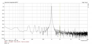
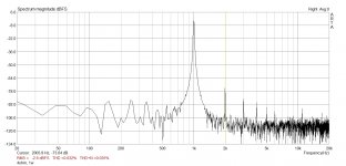
Just managed for the first time to measure THD of my lm1875 amp with lme49720 preamp.
My setup is Creative X-Fi 5.1 USB and Arta sofware, floor THD level is about .004%.
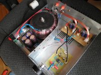
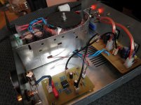
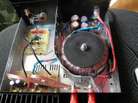
Below pictures with amp itself and what I`ve got in 4 and 8 Ohm. From what I saw in datasheet it's not bad (but I guess can be better), and I am interested in other's opinion and personal experiences. How low can you get with this IC?
Sorry if my English not to good)
Just managed for the first time to measure THD of my lm1875 amp with lme49720 preamp.
My setup is Creative X-Fi 5.1 USB and Arta sofware, floor THD level is about .004%.
Below pictures with amp itself and what I`ve got in 4 and 8 Ohm. From what I saw in datasheet it's not bad (but I guess can be better), and I am interested in other's opinion and personal experiences. How low can you get with this IC?
Sorry if my English not to good)
Attachments
You should be able to meet the data sheet performance if you follow the instructions given in the data sheet and make a good layout. That's been my experience with the LM3886 and the LM1875 is very similar.
Have a look at the table of specifications in the data sheet. If a parameter is listed with a min/max limit in the table, it is tested in production. If your can't meet those specs, I suggest taking a good look at your PCB layout.
Tom
Have a look at the table of specifications in the data sheet. If a parameter is listed with a min/max limit in the table, it is tested in production. If your can't meet those specs, I suggest taking a good look at your PCB layout.
Tom
not sure if it would make a huge difference but i suspect i would move the rectifier board further away from the toroid, maybe even extend the shielding.
wires from the rectifier board to the power amps are not twisted enough, and the speaker cables going from them to the posts are allso non-twisted.
stands true for the signal cables going from the opamp board to the power amp board.
maybe you could add a ferrite bead to them, not sure how mutch would it count.
Thanks for reply!
Tom, yes, I have examined the data sheet, and especially the THD graph, which have practically exact figures that I`ve got in my measurements. Today I revised the amp's PCB layout (I hope for better") and soon will do another board to see what it changed.
and soon will do another board to see what it changed.
Arty, I think you right about the toroid being to close to the PSU board, but it has no impact on THD (I have measured both inside and ouside chassis). And yea, I probably can twist power lines tighter. But why should I twist output cables? I have like 2 metres of cables from the amp to speakers, which isn't twisted. Signal cables are shielded, seperate for two channel (just crossing in the photo)
Tom, yes, I have examined the data sheet, and especially the THD graph, which have practically exact figures that I`ve got in my measurements. Today I revised the amp's PCB layout (I hope for better
and soon will do another board to see what it changed.Arty, I think you right about the toroid being to close to the PSU board, but it has no impact on THD (I have measured both inside and ouside chassis). And yea, I probably can twist power lines tighter. But why should I twist output cables? I have like 2 metres of cables from the amp to speakers, which isn't twisted. Signal cables are shielded, seperate for two channel (just crossing in the photo)
Thanks for reply!
Tom, yes, I have examined the data sheet, and especially the THD graph, which have practically exact figures that I`ve got in my measurements. Today I revised the amp's PCB layout (I hope for better
Exactly what Tom said. I would go here and learn what you can in optimizing the layout. This is mentioned in a few areas but in more detail under the "Grounding" pages. It should help you with your own LM1875 build even though it was written for the LM3886.
Arty, I think you right about the toroid being to close to the PSU board, but it has no impact on THD (I have measured both inside and ouside chassis). And yea, I probably can twist power lines tighter. But why should I twist output cables? I have like 2 metres of cables from the amp to speakers, which isn't twisted. Signal cables are shielded, seperate for two channel (just crossing in the photo)
Bingo! You are correct.
Work on the layout first, everything else mentioned is good ("looks good") but somewhat superfluous when the greater source of your higher THD is most likely the layout in the 1st place.
Good luck to you,
Anand.
Thanks Anand
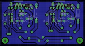
I've built my PCB according to that great site you've adviced me, but now I see that I can do a few improvements, so I came out with this (picture below), just slightly better than it was.
According to my measurements I have about 0.032% THD in 4 Ohm, do you think it's high for this IC?
By the way, I am running this amp with low gain (12dB, if I remember correctly, and 2dB in the preamp), maybe this have an adverse effect on the stability?
I guess, first I should set higher gain and take another THD measurements.
Andriy
Attachments
well, speaker cables are not suspect for picking up stuff and thereby influencing anything, i allso have to mention i did point out what i suggested may not help at all.
but back to the speaker cables near your amp inside the shielded case.
they can radiate,not just pickup.
but back to the speaker cables near your amp inside the shielded case.
they can radiate,not just pickup.
I think the new board layout is quite good as well as the amp layout itself. It would be nice to have the signal injected into the power amp board itself and see the results across the power and frequency bands.
Nice to see the use of a Thiele network on the output. Some may argue the necessity of having it on the LM1875, but it is good practice.
My only quibbles are 1) I see only one screw holding down the power amp board. The IC legs do the rest. I'd use more support. 2) Not clear if you have it, but I'd have RF filtering on the input of the amp.
Thanks johnr66
Between the PCB that currently in my amp and one I've showed above really just a little difference, you even can see this from the photo, so I don't think it will make a big improvement on the THD, but who knows)
Distortion of the premp board itself below my measurement capability, which is 0.004%.
I have added more supports just after first photoset)
And there is no RF filter, I think I will add it to the new board.
Andriy
Attachments
- Status
- This old topic is closed. If you want to reopen this topic, contact a moderator using the "Report Post" button.
- Home
- Amplifiers
- Chip Amps
- Lm1875 THD