This thread is dedicated to applications of lm3886 running at 125°C Tj.
On "Talking about lm3886"thread you can read why this IC is designed to be used at high temperature.You also find as references, uploaded intimate thoughts, of revered gainclone experts.
ARTY " heating an amp ic rarely made it sound better to me.i prefer them as cold as possible within reasonable level.if it gets up to boiling point then the highs become grainy and i don't like that". _________________
AndrewT " I wish I did not follow your precedent and waste my time reading it.I will go and unsubscribe in the hope I don't bump into this Thread again. "
The maximum temperature advised by the datasheet is 150°C, although the thermal shutdown occurs at 165°C to be switched back on safely at 155°C. Running at 125°C leaves a margin of 25°C .Using lm3886tf isolated version which has thermal resistance of 2°C/W+0.2 for thermal compound ,provides about 10W acceptable dissipating power tolerance.
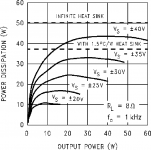
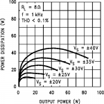
A straight forward idea for constant power dissipation, is class A,but looking on the figure bellow at Vs+/-25v you can see a strange flat curve from 5W to 30W Po the IC dissipates 15W to 17W.
lm3886load.png
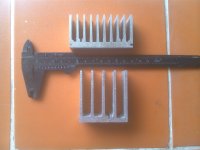
If at 15W dissipation the Tj is 120° to allow at 20W to become 130° with 2.2°C/W ,then the heatsink temperature is to be adjusted about 85° (120-15*2.2) . I tailored two heatsinks shown bellow , adequate for 30° ambient temperature.
heatsink.jpg
Both are 2.5cm thick developing both 200cm.sq.(buttom excl.) surface(air-metal contact).The shorter and wider one above weighs 105gr. It needs about 10mn to heat from 30°to 85°.The other weighs 65gr and requires only 5 minutes and costs half price.
The circuit to be used is non_inverting.For 31W it requires a gain of 23,feedback resistors 22k and 1k wil do,a 33k pulling down the mute to -V ,a 10k potentiometer and a pair of ceramic 100nf decoupling the rails. Power supplies are provided by two switching power supplies 24V3A each, adjusted 25V and you get the best sounding lm3886 ,on condition you are using it above 5W.
If this is suitable for outdoor use ,it is too high power, for use in an apartment.To realize it by yourself,adjust the sound to a comfortable level and mesure with a digital ac voltmeter the voltage on speaker,even with a low efficiency one you will be astonished how the average power is so low.Adjust it to be 5W (6.35v for 8ohms) and realize how loud the amp under design, should run, to be heated properly.
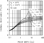
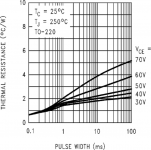
The remedy for this is to use an ordinary fullwave rectifier.If it is designed to provide 25V at 30W output ,then at low power, the supply voltage can go above 30V.On the curves above it shows the amp can dissipate 15W, starting at 2W output. Now new problems arise.At 10W continuous output, the supply is far above 25V,but from the begining of the design, up to 20W disssipation was considered ,but at transients, the supply capacitor's high voltage, charged at idle, must collapse rapidly in order to prevent overheating the output transistors above 250°.Here, the calculations are in jouls.The most important parameter is the dynamic thermal resistance of the output transistors shown on the figure bellow. A simple calculus math. could resolve the problem if it was a linear one.
If the value of the capacitor is decreased to lower stored energy, then the ripples become higher To keep the supply above +/_25V, the ac supply sould be increased ,that means higher energy stored, so to lower the capacitor value ,and so on. By estimation and trials the retained value of the capacitor is 3300uF along ac 2*22.3V (300VA PS transformer for two channels).
Now we have an amp good to function between 2W to 30W.
A parenthesis
******************
OPTIONAL READING
******************
The Gaincard from47Labs, became a reference ,as sea-level or freezing point of water,since a holly hifi magazine qualified it as,top grade.Ever since, IC amps are compared relatively to it.
COMPARING WITH GAINCARD
The Lm3875 used in Gaincard, needs to be heated Tj of 135° to have the thermal feedbacks canceled , instead of 125°, see figures bellow,Then the heatsink temperature must be 95°instead of 85°.
lm3886. lm3875
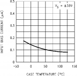
lm3886bias.png. lm3875bias.png
Running at the same operating condition, the Gaincard delivers 25W instead of 30W.
lm3886. lm3875
lm3886load.png. lm3875load.png
The dynamic thermal resistance being much higher,the Gaincard uses 1000uF capacitors with 2*23.6V ac instead of 3300uF 2*22.3Vac.This may be, results in lower dynamic sound (not shure).
lm3886 lm3875
Where the Gaincard excels, is at heatsink.It uses a tiny aluminum enclosure (10cm*8cm*4cm) with aboutt 2mm thick upper and lower plates linked firmly (thermally) by a 5mm thick side.
see the pictures of the heatsink dismentled.
http://www.6moons.com/audioreviews/47labs5/gaincard.html
The total radiating surface is 200cm.sq. But with the two heatsinks joint together, the bottoms are effective only by half ,this reduces the radiating surface to 160cm.sq. 15W dissipation highers the temperature from 30° amb. to 95°.
As the IC is mounted on the thin bottom plate, It creates a hot spot of 95° to be reduced to 60°-70° on the upper edje.With such heatsink primo,children are not injured accidentely,secondo it provides lower thermal inertia to reach 95°in less than 3 minutes.
*Gaincard temperatures are calculated/estimated for Tamb of 30°C.
**************
End of parenthesis
There are two more problems to resolve. 5minutes or 2 minuets ,it is still too long to heat up.The most important is still at low power.If you are listening as background music while reading or dinnig or simply it is late evening and you are listening a soothing music ,The amp will remain cold and provide you toy quality sound.
One step beyond.
How about powering this IC to its maximum voltage +/-40V.If I can provide 150ma at this voltage by a high impedance supply added uppon, then I get 15W dissipation at the first watt.
But who will swallow the 150ma if their is no signal?The IC will take it's share of 50-80ma,what is left, is taken by a pair of power zeners.The total power dissipated at quiescent now is 12W.How about I give a hand and make it 15W.By this the heatsink once heated to 85°it remains constant.
Signal,or not signal,is no more a question.As the IC dissipates at quiescent 4W the Tj min is about 95°.Just tiny watts and it goes to hell° and this, up to 30W output.
To make a high impedance supply toppling a full wave ,is to add a pair of capacitors across the bridge and add two diodes in series to transform the PS into a weak tripler.The values of the capacitors fix the supplementing current.47uF+(33uF/50Hz or 22uF/60Hz) .See the circuit bellow.
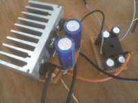
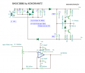
Basic3886circuit.png
basic3886.jpg
Yes the BASIC3886 is the 300B of semiconductors.Now it just got a power supply.Similar to 300B which requires also an adequate nonlinear driver and a decent output transformer to be called an audio amp,the BASIC3886 also needs some auxiliaries to deserve the title of 21st century audio amplifier.
THE BEST IS YET TO COME
KOKORIANTZ
Curves are extracted from TI datasheet.
On "Talking about lm3886"thread you can read why this IC is designed to be used at high temperature.You also find as references, uploaded intimate thoughts, of revered gainclone experts.
ARTY " heating an amp ic rarely made it sound better to me.i prefer them as cold as possible within reasonable level.if it gets up to boiling point then the highs become grainy and i don't like that". _________________
AndrewT " I wish I did not follow your precedent and waste my time reading it.I will go and unsubscribe in the hope I don't bump into this Thread again. "
The maximum temperature advised by the datasheet is 150°C, although the thermal shutdown occurs at 165°C to be switched back on safely at 155°C. Running at 125°C leaves a margin of 25°C .Using lm3886tf isolated version which has thermal resistance of 2°C/W+0.2 for thermal compound ,provides about 10W acceptable dissipating power tolerance.
A straight forward idea for constant power dissipation, is class A,but looking on the figure bellow at Vs+/-25v you can see a strange flat curve from 5W to 30W Po the IC dissipates 15W to 17W.
lm3886load.png
If at 15W dissipation the Tj is 120° to allow at 20W to become 130° with 2.2°C/W ,then the heatsink temperature is to be adjusted about 85° (120-15*2.2) . I tailored two heatsinks shown bellow , adequate for 30° ambient temperature.
heatsink.jpg
Both are 2.5cm thick developing both 200cm.sq.(buttom excl.) surface(air-metal contact).The shorter and wider one above weighs 105gr. It needs about 10mn to heat from 30°to 85°.The other weighs 65gr and requires only 5 minutes and costs half price.
The circuit to be used is non_inverting.For 31W it requires a gain of 23,feedback resistors 22k and 1k wil do,a 33k pulling down the mute to -V ,a 10k potentiometer and a pair of ceramic 100nf decoupling the rails. Power supplies are provided by two switching power supplies 24V3A each, adjusted 25V and you get the best sounding lm3886 ,on condition you are using it above 5W.
If this is suitable for outdoor use ,it is too high power, for use in an apartment.To realize it by yourself,adjust the sound to a comfortable level and mesure with a digital ac voltmeter the voltage on speaker,even with a low efficiency one you will be astonished how the average power is so low.Adjust it to be 5W (6.35v for 8ohms) and realize how loud the amp under design, should run, to be heated properly.
The remedy for this is to use an ordinary fullwave rectifier.If it is designed to provide 25V at 30W output ,then at low power, the supply voltage can go above 30V.On the curves above it shows the amp can dissipate 15W, starting at 2W output. Now new problems arise.At 10W continuous output, the supply is far above 25V,but from the begining of the design, up to 20W disssipation was considered ,but at transients, the supply capacitor's high voltage, charged at idle, must collapse rapidly in order to prevent overheating the output transistors above 250°.Here, the calculations are in jouls.The most important parameter is the dynamic thermal resistance of the output transistors shown on the figure bellow. A simple calculus math. could resolve the problem if it was a linear one.
If the value of the capacitor is decreased to lower stored energy, then the ripples become higher To keep the supply above +/_25V, the ac supply sould be increased ,that means higher energy stored, so to lower the capacitor value ,and so on. By estimation and trials the retained value of the capacitor is 3300uF along ac 2*22.3V (300VA PS transformer for two channels).
Now we have an amp good to function between 2W to 30W.
A parenthesis
******************
OPTIONAL READING
******************
The Gaincard from47Labs, became a reference ,as sea-level or freezing point of water,since a holly hifi magazine qualified it as,top grade.Ever since, IC amps are compared relatively to it.
COMPARING WITH GAINCARD
The Lm3875 used in Gaincard, needs to be heated Tj of 135° to have the thermal feedbacks canceled , instead of 125°, see figures bellow,Then the heatsink temperature must be 95°instead of 85°.
lm3886. lm3875
lm3886bias.png. lm3875bias.png
Running at the same operating condition, the Gaincard delivers 25W instead of 30W.
lm3886. lm3875
lm3886load.png. lm3875load.png
The dynamic thermal resistance being much higher,the Gaincard uses 1000uF capacitors with 2*23.6V ac instead of 3300uF 2*22.3Vac.This may be, results in lower dynamic sound (not shure).
lm3886 lm3875
Where the Gaincard excels, is at heatsink.It uses a tiny aluminum enclosure (10cm*8cm*4cm) with aboutt 2mm thick upper and lower plates linked firmly (thermally) by a 5mm thick side.
see the pictures of the heatsink dismentled.
http://www.6moons.com/audioreviews/47labs5/gaincard.html
The total radiating surface is 200cm.sq. But with the two heatsinks joint together, the bottoms are effective only by half ,this reduces the radiating surface to 160cm.sq. 15W dissipation highers the temperature from 30° amb. to 95°.
As the IC is mounted on the thin bottom plate, It creates a hot spot of 95° to be reduced to 60°-70° on the upper edje.With such heatsink primo,children are not injured accidentely,secondo it provides lower thermal inertia to reach 95°in less than 3 minutes.
*Gaincard temperatures are calculated/estimated for Tamb of 30°C.
**************
End of parenthesis
There are two more problems to resolve. 5minutes or 2 minuets ,it is still too long to heat up.The most important is still at low power.If you are listening as background music while reading or dinnig or simply it is late evening and you are listening a soothing music ,The amp will remain cold and provide you toy quality sound.
One step beyond.
How about powering this IC to its maximum voltage +/-40V.If I can provide 150ma at this voltage by a high impedance supply added uppon, then I get 15W dissipation at the first watt.
But who will swallow the 150ma if their is no signal?The IC will take it's share of 50-80ma,what is left, is taken by a pair of power zeners.The total power dissipated at quiescent now is 12W.How about I give a hand and make it 15W.By this the heatsink once heated to 85°it remains constant.
Signal,or not signal,is no more a question.As the IC dissipates at quiescent 4W the Tj min is about 95°.Just tiny watts and it goes to hell° and this, up to 30W output.
To make a high impedance supply toppling a full wave ,is to add a pair of capacitors across the bridge and add two diodes in series to transform the PS into a weak tripler.The values of the capacitors fix the supplementing current.47uF+(33uF/50Hz or 22uF/60Hz) .See the circuit bellow.
Basic3886circuit.png
basic3886.jpg
Yes the BASIC3886 is the 300B of semiconductors.Now it just got a power supply.Similar to 300B which requires also an adequate nonlinear driver and a decent output transformer to be called an audio amp,the BASIC3886 also needs some auxiliaries to deserve the title of 21st century audio amplifier.
THE BEST IS YET TO COME
KOKORIANTZ
Curves are extracted from TI datasheet.
Attachments
-
 basic3886.jpg515.3 KB · Views: 1,304
 -
 Basic3886circuit.png717.6 KB · Views: 1,296
 -
 heatsink.JPG919.7 KB · Views: 1,249
 -
 lm3875bias.png27.2 KB · Views: 1,202
 -
 lm3875dr.png52.8 KB · Views: 1,184
 -
 lm3875load.png17.7 KB · Views: 120
 -
 lm3886bias.png26.2 KB · Views: 105
 -
 lm3886dr.png112 KB · Views: 99
 -
 lm3886load.png20.2 KB · Views: 102
Just beware that the chip reliability declines dramatically at high temperatures.
Regardless of operating temperature, I encourage you to include the components necessary for good stability near the rail: Cc, Rf2, Cf mentioned in the data sheet, necessary for good stability with capacitive load: Cz, Rz, and Thiele network L||R on the output. Furthermore, I strongly suggest following the data sheet guidelines for decoupling. With the 100 nF you have in your schematic, the chip will oscillate once you drive the output voltage beyond 30 V RMS.
Tom
well, your problem if you like your gainclones fried,
i don't want to get in that. really.
but since its DIY and whatever suits you, suits YOU, i think i have a hint for You.
You could use a heater element in order to keep your chips nice and boiling.
stuff heating up and cooling down is.. not too healthy.
the high temp. alone is nt healthy to begin with.
but a lot of stress from expanding from heat than shrinking back to normal is absolutely a killer.
better keep it at a steady temp then, at least you don't have to get too close to rail limits, and most probably turn on wait time will be shorter.
allso i don't advise anyone on heating any chip or letting it run on high temp.
THE BASIC3886
An externally hosted image should be here but it was not working when we last tested it.
A request from tomchr
To predict the reliability of a component ,you need to have the MTBF (mean time before failure) curves.But these curves are not available for LM3886, which means ,you used a crystal ball dedicated for "electronics astrology".
So I humbly ask his "Honorable mage" if he can also predict by how many years the LM3886 at125°C IS MORE RELIABLE THAN THE GAINCARD amp. which runs its LM3875 at 135°C .
Output voltage 30vrms=42volt peak +2.5volt for output dropout =44.2 power supply /rail.Maximum limit is +/-42 The output transistors are distroyed at 42Volts .You are very lucky to be able seeing them oscillate.
Each channel requires its own proprietary power supply, so it can adapt indipendently according to the its own output serving power.Everyting from bridge rectifier and on ,each channel must have its own .Of course ,The transformer and all before are common .This applies also for the (second) gaincard type solution .
47Labs advises to use individual power supply of 170VA for each channel, guess why.
47Labs advises to use individual power supply of 170VA for each channel, guess why.
Tomchr. I am sorry about MTBF
On TI site I found the MTBF data of LM3886tf.
http://www.ti.com/quality/docs/estimator.tsp?OPN=LM3886TF&CPN=&partNumber=Lm3886#resultstable
You can read ,the circuit tested at 125°C has a reliability of 138 MILLION hours.
KOKORIANTZ
On TI site I found the MTBF data of LM3886tf.
http://www.ti.com/quality/docs/estimator.tsp?OPN=LM3886TF&CPN=&partNumber=Lm3886#resultstable
You can read ,the circuit tested at 125°C has a reliability of 138 MILLION hours.
KOKORIANTZ
For the experiment you could run a temp controlled fan to regulate HS temperature and compare listening at different operating temps.
Understand that device noise goes up with temperature - Noise in Semiconductor Devices
Dan.
Understand that device noise goes up with temperature - Noise in Semiconductor Devices
Dan.
http://www.diyaudio.com/forums/chip...6-kit-review-measurements-27.html#post4829201
Picture 3 and 4
3. harmonic distortion goes up as the chip gets hotter it seems. Maybe they like the extra shimmer from the harmonics. Don't think the chip i measured without and with "double sided insulating heat transfer tape" was that hot, so I guess the distortion can get higher with an even hotter chip.
Why not use cheap ceramic caps to create the distortion instead.
To predict the reliability of a component ,you need to have the MTBF (mean time before failure) curves.But these curves are not available for LM3886, which means ,you used a crystal ball dedicated for "electronics astrology".
That is true. However, I did spend a decade of my life working for National Semiconductor (and TI after the acquisition), so I do have some knowledge of how temperature affects part reliability as I was responsible for ensuring that my circuits met the requirements for reliability. Your use of ALL-CAPS is no substitute for facts or knowledge.
That said, it is your hobby and your circuit. You're obviously free to do whatever you want, including doing everything to shoot yourself in the foot. However, as you asked for feedback on your idea, I figured I would be rather negligent if I didn't at least make you aware that you are shooting yourself in the foot. I suppose it's your foot and you're paying the ammunition, so maybe I shouldn't care. If that is your opinion, then it begs the question why you asked for feedback here in the first place. "Please let me know your feedback, but only if you are willing to reinforce me in my belief that this idea is the greatest thing since sliced bread".
Now, assuming you are proceeding with this idea, I am curious how you plan to keep the LM3886 operating just below the onset of tripping the thermal shutdown when the amount of power dissipated in the LM3886, hence, its temperature will depend on the input signal. How are you planning to avoid having the SPiKe protection and/or thermal shutdown engage when you have the relatively slow thermal system of the IC package and heat sink beating against the much faster thermal time constant of the thermal system on die?
Tom
Why not use cheap ceramic caps to create the distortion instead.
Or a DSP.
Tom
For the experiment you could run a temp controlled fan to regulate HS temperature and compare listening at different operating temps.
I find myself reminded of the experiments done in physics class. You know... Thermos with hot water and some temperature controller. Use one of those and dunk the LM3886 heat sink into it. Vary the temperature and listen/measure the differences.
Understand that device noise goes up with temperature
Noise goes up. Most device parameters degrade. I say "most". I can't actually think of any parameter that improves with higher temperature, but that's not to say you can't find one. The amplifier's open loop gain gain tends to drop at higher temperature as well as the ft of the various devices tends to roll off quite steeply once the temperature exceeds 100-120 ºC. This results in worse performance overall.
Tom
I do not pretend to have enough knowledge in electronics to make a comment regarding design but it seems there is a purposeful refusal to read that he says the 47 LABS GAINCARD runs at a high temperature and is regarded to sound very good. Good enough to launch a thousand gainclone projects.
I would think if there were failures with this device it would have become audio folklore by now so i am baffled by the comments based upon there being some mystery to solve here. There is a commercial product that performs well in the field. How can this be some crazy "audiophile" idea?
It is obviously part of the design that all of the previous "cloners" had not noticed. Only experience of those trying it will tell us if this important for the sound of the things or not. Though when one considers the engineering decisions that the engineers tell us about: why would someone put out a product with such a "dangerous" power arrangement to sell around the world knowing the most important part of the circuit will surely blow up? It is not as if the 47 LABS works out of someone's kitchen. Not that I have anything against amplifiers built on a kitchen table since that is what i use. But I suspect they warranted these things and would want to minimize their losses from failing amplifiers. Some manufacturers are famous for taking chances but in the past tense. The reputations outlive them. 47 LABS is still here and if kokoriantz is correct, still making GAIN CARDS that run the chips at high temperatures.
If I was still using the LM3875 I would try this out as soon as I could. I ran mine on a 1/4 inch copper plate of about 10 x 4 inches and I never felt any heat from the plate. They were not used below 100 hz.
This is such a neat inexpensive device that brings good sound to lots of people who would otherwise use something much worse due to budget concerns.
Why not try to find how to get the most out of it? Akin to not really knowing how far a car will go on a tank of gas/petrol until it runs out. Until you burn a chip or two what do you really know about it? Probably just what the data sheet says.
I admire kokoriantz's intrepidity and observation abilities. Wish I had as much.
I do not pretend to have enough knowledge in electronics to make a comment regarding design but it seems there is a purposeful refusal to read that he says the 47 LABS GAINCARD runs at a high temperature and is regarded to sound very good.
Great. Is it regarded to sound good because the LM3886 runs at high temperature or is there something else in the design that causes the high regard for the sound quality?
Correlation != causation.
Why not try to find how to get the most out of it?
No argument from me. However, if you are aiming to get the most out of the LM3886, you'd be better off throwing engineering at the problem. See my Modulus-86 for an example.
Tom
Last edited:
- Status
- Not open for further replies.
- Home
- Amplifiers
- Chip Amps
- LM3886 singing at hell°