I have never built an amplifier before, and the thought powering up a board I soldered along with all the associated mains and toroidal transformer wiring had me feeling a little anxious when I flipped the switch.

Low and behold, no magic smoke was emitted and everything tested as it should.
So far, so good...
")
Low and behold, no magic smoke was emitted and everything tested as it should.
So far, so good...
As I was looking at the next step, wiring up the power board to the amps, I realized it was not as straightforward as I thought it was.
Does this diagram look correct?

It would be easier to use the terminals in the middle of the power board (less spaghetti) , but I don't think the mating connectors were on the bill of materials.
Does this diagram look correct?
It would be easier to use the terminals in the middle of the power board (less spaghetti) , but I don't think the mating connectors were on the bill of materials.


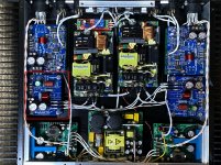
Well my Neurochrome LM3886DR is all built now!


I did my best to keep all the wires separate and not parallel. Ended up using Mogami coaxial for the run from the 10K Alps pot to the amps, but the run from the inputs was too short to use it, so I used some short bits of 22g twisted solid strand.
The power wires ended up braided just because I don't like zip ties.
Amp to speaker outs is 16g twisted solid core.
The only thing left to do is connect a source and some speakers to see how it sounds. (don't worry, I will test with an old crap 6x9 car speaker before connecting a real pair of speakers)
Before I do try it though, does anyone see any obvious mistakes I have made, or things I should correct?
Be nice, this is the first amp I have built, and without such an easy kit with access to Tom, I don't think I could have done it.
Thanks Tom!
Last edited:
Yeah... An electronics teacher of mine of years past referred to the chassis as "the last 10% of the project that takes the last 90% of the time".
That's one of the reasons I've started to have ModuShop (and others) deliver the chassis with all the holes cut and threaded. I love being able to put together an amp in half a day instead of in a few weekends. But... It is more expensive. They don't work for free.
Tom
That's one of the reasons I've started to have ModuShop (and others) deliver the chassis with all the holes cut and threaded. I love being able to put together an amp in half a day instead of in a few weekends. But... It is more expensive. They don't work for free.
Tom
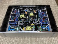
This is my 8 channel amp for the LX521 active 4-way. While it uses 4 each of Tom’s Mod86 and LM3886DR, plus 2 Hypex modules, I’m posting here because of the bridged implementation of the LM3886DR’s. All of my goals were realized, but I am hoping to get a little feedback regarding a small noise issue.
The goals were to cram 8 balanced-input channels into an existing compact chassis, with power matched to the needs of each driver via Speakon NL8 outputs. I used UCD400 for 2Ω woofers, bridged LM3886DR’s for 8Ω lower-mid, Mod86 each for 4Ω upper-mid and 8Ω tweeters.
SMPS were the only option from a packaging perspective. Lack of spacing to prevent noise pick up and heat were the main concerns. Thanks to Tom for giving me the confidence to try the Mean Well modules, without which the project would be a non-starter.
Bridged LM3886DR - I opted to uses these modules for the following reasons:
-a Bryston 2B-SST (100wpc) previously used for midrange, was only rarely driven to clipping; so I hoped the 8Ω driver was within the capability of bridged LM3886’s
-space limitations within the chassis
-using only a differential source, I thought why can’t I directly bridge 2 single ended modules (no inverters or receivers); I had not seen this done, so I asked Tom who responded, “it should work”!
I assembled the boards to spec, except the connectors, and used <.1% matched resistors for gain setting (29dB) and input impedance. The shielded twisted pair from the XLR splits right at the module inputs (the shield connected to only one board). Initially I wondered if the gain would need to be halved because they are bridged, but the differential input halves the voltage to each board so the overall gain is unchanged, and measures precisely the same 29dB as the Mod86’s. The LM3886 chips from one batch all have 4-5mV DC offset. Bridged pairs have <1mV offset from cold to hot. With (2)Mean Well EPP-400 28v regulated rails they produce ~120w into 8Ω test load before any signs of clipping. Happily this is just a bit higher than the Bryston.
Heat: Clipping tests of bridged channels quickly heat up the heatsinks and can get too hot to hold, but during spirited listening sessions the heatsinks rarely exceed 50°C. I am watchful and still evaluating air temperature around the SMPS as the chassis is packed and the vents are not directly above or below them.
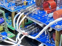
Noise: The (4) Mod86 channels are very quiet, particularly given the 29dB gain, only a clean faint hiss with an ear an inch from the driver, zero hum. The left bridged LM3886DR pair is about as quiet but with a hint of “sputter” character to the hiss. The right bridged pair is a bit louder with a more clearly defined RF/sputter-like character) being able to hear it 4-5” from the driver. The noise is consistent over time, and again, no audible 60Hz component.Unfortunately I only have a PC-based oscilloscope which insufficient resolution to Identify the specific frequency. No change occurs with the source and the Hypex components disconnected, nor swapping the Mean Well module positions. I mounted the SMPS on a sub-plate to facilitate moving the pair 5-10 mm in any direction, and left room around the modules for (copper?) shielding thinking that may be helpful due to the close quarters. I tried positioning a temporary shielding plate (sheet metal with ground wire) between the amp and SMPS but could not detect any improvement. I'm hoping this is an issue other builders may have found solutions to, or at least suggests techniques to better identify it.
Summary: The bridged LM3886DR output lives up to the predicted performance. The total package is working as planned and sounds great. Of course Tom's interest and attentiveness, as well as the PCB's are first rate. The noise asymmetry and character, as opposed to its audibility, and the fact it's the ONLY issue that turned up, does bug me, so any suggestions would be greatly appreciated. Thanks.
The goals were to cram 8 balanced-input channels into an existing compact chassis, with power matched to the needs of each driver via Speakon NL8 outputs. I used UCD400 for 2Ω woofers, bridged LM3886DR’s for 8Ω lower-mid, Mod86 each for 4Ω upper-mid and 8Ω tweeters.
SMPS were the only option from a packaging perspective. Lack of spacing to prevent noise pick up and heat were the main concerns. Thanks to Tom for giving me the confidence to try the Mean Well modules, without which the project would be a non-starter.
Bridged LM3886DR - I opted to uses these modules for the following reasons:
-a Bryston 2B-SST (100wpc) previously used for midrange, was only rarely driven to clipping; so I hoped the 8Ω driver was within the capability of bridged LM3886’s
-space limitations within the chassis
-using only a differential source, I thought why can’t I directly bridge 2 single ended modules (no inverters or receivers); I had not seen this done, so I asked Tom who responded, “it should work”!
I assembled the boards to spec, except the connectors, and used <.1% matched resistors for gain setting (29dB) and input impedance. The shielded twisted pair from the XLR splits right at the module inputs (the shield connected to only one board). Initially I wondered if the gain would need to be halved because they are bridged, but the differential input halves the voltage to each board so the overall gain is unchanged, and measures precisely the same 29dB as the Mod86’s. The LM3886 chips from one batch all have 4-5mV DC offset. Bridged pairs have <1mV offset from cold to hot. With (2)Mean Well EPP-400 28v regulated rails they produce ~120w into 8Ω test load before any signs of clipping. Happily this is just a bit higher than the Bryston.
Heat: Clipping tests of bridged channels quickly heat up the heatsinks and can get too hot to hold, but during spirited listening sessions the heatsinks rarely exceed 50°C. I am watchful and still evaluating air temperature around the SMPS as the chassis is packed and the vents are not directly above or below them.
Noise: The (4) Mod86 channels are very quiet, particularly given the 29dB gain, only a clean faint hiss with an ear an inch from the driver, zero hum. The left bridged LM3886DR pair is about as quiet but with a hint of “sputter” character to the hiss. The right bridged pair is a bit louder with a more clearly defined RF/sputter-like character) being able to hear it 4-5” from the driver. The noise is consistent over time, and again, no audible 60Hz component.Unfortunately I only have a PC-based oscilloscope which insufficient resolution to Identify the specific frequency. No change occurs with the source and the Hypex components disconnected, nor swapping the Mean Well module positions. I mounted the SMPS on a sub-plate to facilitate moving the pair 5-10 mm in any direction, and left room around the modules for (copper?) shielding thinking that may be helpful due to the close quarters. I tried positioning a temporary shielding plate (sheet metal with ground wire) between the amp and SMPS but could not detect any improvement. I'm hoping this is an issue other builders may have found solutions to, or at least suggests techniques to better identify it.
Summary: The bridged LM3886DR output lives up to the predicted performance. The total package is working as planned and sounds great. Of course Tom's interest and attentiveness, as well as the PCB's are first rate. The noise asymmetry and character, as opposed to its audibility, and the fact it's the ONLY issue that turned up, does bug me, so any suggestions would be greatly appreciated. Thanks.
Attachments
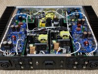

Dang! You squeezed a lot of sardines into that can! Nice work. I like how all boards are supported. Also neat trick with the spade connectors on the Molex footprint.
As for the supply noise on the LM3886DR channels: The 'naked' LM3886 does not have great PSRR, so that could be what you're experiencing. I would try adding an LC filter on the supply to the LM3886DRs. You'll want a filter that offers meaningful attenuation at the switching frequency of the SMPS while not degrading the output impedance of the SMPS within the audio band. So you'll probably end up with a cutoff frequency in the 1-10 kHz range as the best compromise.
Given that you don't have a lot of room for additional components, I suggest focusing on the negative rail first. That's where the LM3886 has the lowest PSRR.
The reason the MOD86 works better is that the composite architecture of the MOD86 provides error correction, which basically eliminates the supply noise.
Tom
Last edited:
Tom - Thank you for reading through my post and your tip of looking at rail vs. airborne contamination.
-Does the chip's PSSR "typical" to "limit" range apply to rail noise, possibly causing one chip within spec to be audibly worse? I never realized PSSR applied to noise rejection. I have spare LM3886's I could change out if it were a randomly noisy one (before trying an LC filter). As noted, the left pair are nearly as quiet as the Mod86's and 99.9% satisfactory.
-Are you thinking it's SMPS-specific noise or extraneous noise coming through the supply? SMPS noise shouldn't have a "sputter" character to it, or could it?
Thanks again.
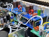
Is what I've circled in the attached image what you consider the left LM3886DR?
PSRR = power supply rejection ratio. It is measured by applying an AC voltage in series with the power supply rail and measuring the perturbation on the amp output. If you have any noise or other AC signal on the power supply rails, some of it will make it through to the output of the amp. I doubt you'll notice any difference between individual samples of LM3886.
In addition, the amp generates its own noise. Electrons move randomly and that creates noise. Some electrons get stuck in traps (usually impurities in the devices) and take a while to get dislodged. That causes the 1/f component you see in noise plots. That's a different topic than PSRR, though.
Do you have the option of trying with a different power supply? Are you running the LM3886DR at its default 26 dB gain?
Given that the left and right channels behave differently but are fed from the same supply, I'm thinking you're having issues with noise coupling rather than conducted noise. The left input connection is right by the SMPS. Are you able to turn the left LM3886DR upside down for a quick test?
Tom
Attachments
I realize my last post obscured that it’s the RIGHT pair that’s noisy.
-Yes, you’ve circled my left channel, which is the good side.
-Thanks for the PSRR specifics.
-I do have a linear supply (from before adding the extra channels) and can give it a try.
-Gain is set to 29dB for all modules.
-Yes, the LM3886DR modules can be detached and moved around a bit, but I’ve not tried that yet. But interestingly, the noisy pair on right has less SMPS proximity.
Thank you.
I realize my last post obscured that it’s the RIGHT pair that’s noisy.
Ah. I'm sure I did read that in your longer post from the other day, but promptly swapped left and right. I'm rather left/right confused. My bad.
-Yes, you’ve circled my left channel, which is the good side.
I see. I'll direct the rest of my comments towards the non-left side, then.
But interestingly, the noisy pair on right has less SMPS proximity.
Yeah. There went that theory. However, it does give rise to another theory: Could it be that UcD couples into the LM3886DR? Do you have a way to turn the UcD off while leaving the rest on? Preferably by disconnecting its power supply.
Tom
Gregg,
Super nice build!
Best,
Anand.
Thanks for the kind words. It was one of the few fun things facilitated by Covid-19.
Thanks for the kind words. It was one of the few fun things facilitated by Covid-19.
You and me both, actually. I've caught up on a bunch of back burner projects. If this continues I may have to write/update my business plan or something.
Are the offending LM3886DRs the bridged ones? If so, I would try to test them one at a time. Perhaps you had the same thought when you mentioned isolating the amps.
Tom
Difficult times for sure, I hope the smiley face means you have decent options.You and me both, actually. I've caught up on a bunch of back burner projects. If this continues I may have to write/update my business plan or something.
Yes, the (4) LM3886DR's are bridge pairs. None are used single-ended.Are the offending LM3886DRs the bridged ones? If so, I would try to test them one at a time. Perhaps you had the same thought when you mentioned isolating the amps.
I'm comfortable troubleshooting, and understand isolating stages is likely what's needed.
Really my query was:
1- if the type of noise I hear sounded of SMPS origin,
2- if the Mean Well units* radiate high frequency EMI from a specific area of the module, where my layout increases the potential for proximity coupling,
3- if the physical separation of the stacked bridged-boards, or my input wiring scheme, makes it hyper-susceptible to EMI.
*I'm using the EPP-400-27 as opposed to the low-EMI rated RPS-400-27 because I got them dirt cheap.
Thank you for your time,
Gregg
- Home
- Amplifiers
- Chip Amps
- Neurochrome LM3886DR Build