Hey guys. I'm hoping someone with some know how would be willing to help me out here. I was recently given a Polk PSW202 subwoofer. When you turn it on there is a loud pop and subwoofer cone moves pretty far. From there regardless of volume or source there is a loud hum followed by a rumble/cracking noise. There is no audio actually getting to the subwoofer from the line in.
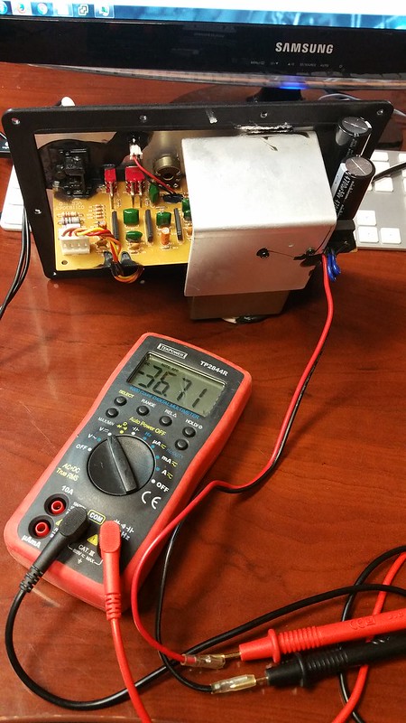
When I hooked up a DMM to the speaker leads and set it to DCV i get -30 to -37 volts on the output (seems regardless of volume on the amp). I'm guessing it shouldn't be spewing DC voltage to the driver? I know the driver is ok cause i hooked it up to another amp and it plays just fine.
I read this specific subwoofer had the wrong value caps in the power filter (i believe it was power filter caps anyways). They were supposed to be 50v 4700uF but polk put in 35v 4700uF caps.
First thing i did was crack the sub open and sure enough there were 35v caps. I pulled them out and they looked OK but i figured I would have to replace them anyways so i ordered the proper caps.
I hoped this would resolve the issue but it did not. I replaced the caps yesterday and it still does the same thing.
I checked and the fuse isn't blow, the IC looks like it's in good shape cosmetically but I know that was another component Polk would replace since the wrong value caps tended to destroy the IC.
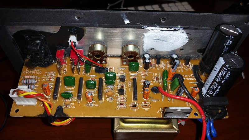
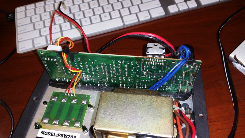
Here are pictures of the board (sorry for my TERRIBLE solder job on the caps. They are too big and I need to flip one to the bottom or something. I will clean it up when the amp is working and I'm ready to reassemble)
I went ahead and ordered an new TDA7294v from digi key since it was cheap. However now i'm worried I may have just wasted money on this. I'm really not very knowledgeable on this sort of thing. I know my way around crossover networks but amp circuitry isn't something i'm all that great with. Any suggestions?
When I hooked up a DMM to the speaker leads and set it to DCV i get -30 to -37 volts on the output (seems regardless of volume on the amp). I'm guessing it shouldn't be spewing DC voltage to the driver? I know the driver is ok cause i hooked it up to another amp and it plays just fine.
I read this specific subwoofer had the wrong value caps in the power filter (i believe it was power filter caps anyways). They were supposed to be 50v 4700uF but polk put in 35v 4700uF caps.
First thing i did was crack the sub open and sure enough there were 35v caps. I pulled them out and they looked OK but i figured I would have to replace them anyways so i ordered the proper caps.
I hoped this would resolve the issue but it did not. I replaced the caps yesterday and it still does the same thing.
I checked and the fuse isn't blow, the IC looks like it's in good shape cosmetically but I know that was another component Polk would replace since the wrong value caps tended to destroy the IC.
Here are pictures of the board (sorry for my TERRIBLE solder job on the caps. They are too big and I need to flip one to the bottom or something. I will clean it up when the amp is working and I'm ready to reassemble)
I went ahead and ordered an new TDA7294v from digi key since it was cheap. However now i'm worried I may have just wasted money on this. I'm really not very knowledgeable on this sort of thing. I know my way around crossover networks but amp circuitry isn't something i'm all that great with. Any suggestions?
thanks for the input. I was hoping it would be as "simple" as just the cap replacement and chip replacement since those are pretty easy and cheap. I definitely wouldn't run it without the heatsink, just took it off to evaluate the condition of the IC and for pictures.
Total noob question here but what do you mean by powering it with a bulb tester?
Total noob question here but what do you mean by powering it with a bulb tester?
It does sound like one of the output transistors in the chip is shorted.
It also sounds like there's a chance that your woofer isn't destroyed. Consider yourself lucky.
When you desolder the chip, power up the board and check voltages at the pins. It's easy to figure out what the voltages should be by looking at the schematic. If one of the voltages is off, your amp still won't work right.
ok, I will try that as well. The woofer is still OK (no idea how since it's been getting tons of DC voltage cranked into it) but yes I'm considering that VERY lucky. I'm going to go ahead and desolder the IC. I don't have access to the amp schematics but when I power it on can I just test each empty hole with the DMM in DC voltage? not sure which are ground and which should carry the voltage.
Total noob question here but what do you mean by powering it with a bulb tester?
Bulb tester is just a rig that connects an incandescent bulb in series with the mains. Not only does it protect the circuit from instant destruction, but it tells you a whole lot about what's going on. The bulb should get bright on power up, then dim. If it stays bright, there's a short. If the bulb flashes, there's oscillation. The bulb will limit max power output (great for your test) and should flash with the music like an old fashioned light organ. It's a great diagnostic tool, and you can build it for free with leftovers from your home renovation projects.
Good to know, I will have to look into that. I still will try and see what the different lines were supposed to be on that 7294 chip. I've removed it from the PCB and i'm guessing there is no way to test it on its own?
I just told you how.
Edit: you could build a protoboard circuit to test it, but it's hardly worth it. I wouldn't put it back in, but I would test the board. If there's a problem somewhere else in the circuit, then it still won't work.
Last edited:
Also, the fact that 35 volt capacitors were used on a circuit that measured 37 volts no load should give you an idea just how marginal this build is. I'd take a look at the other components in the circuit (especially the electrolytic capacitors, always cheap in cheap equipment). Now's your chance to make it better. It'll last longer if you replace marginal or questionable components.
So I got the new TDA7924v in and soldered it to the board. Sadly the amp is doing the same thing. I guess something else is wrong with the board. I don't know which pins to test or how to do that safely with the amp powered on (again, super super limited in my knowledge of electronics here) so I'm just gonna give up on this amp for now. I may outfit the enclosure with a cheap replacement plate amp from Parts Express or something.
Thanks for your guys help.
Thanks for your guys help.
Have you checked the supplies to the TDA ? It will use a circuit similar to this.

Pins 7 and 13 should be plus say 40 volts (whatever it runs on) and pins 8 and 15 should be same but a minus voltage. Be very careful not to short anything... and you really need to measure at the chip to rule out broken/cracked prints and so on.
Pins 7 and 13 should be plus say 40 volts (whatever it runs on) and pins 8 and 15 should be same but a minus voltage. Be very careful not to short anything... and you really need to measure at the chip to rule out broken/cracked prints and so on.
I don't mind giving it a whirl. Which pin is 1 on the TDA? I couldn't tell from the diagram I saw online if it was the front side or back (back being the side that attaches to the heatsink) can I measure from the back side of the PCB instead of on the chip I know it doesn't rule out a bad pin or solder joint but the heatsink wraps around the chip so i can't get to anything. Sorry for being a total noob here. I've done lots of soldering of speaker crossovers but that's the extent of it for me so anything amp related is a total mystery.
Last edited:

There was no washer on the amp. The ic is clamped to the metal heat sink via a metal plate and screws.
I did power up the amp and test those pins. I assumed pin 1 was on the left side of the chip if you are looking at it with the plastic side with the chip number on it. I got 0v on both those pin sets so I either did it wrong or something is messed up.
I did power up the amp and test those pins. I assumed pin 1 was on the left side of the chip if you are looking at it with the plastic side with the chip number on it. I got 0v on both those pin sets so I either did it wrong or something is messed up.
here are some pictures.
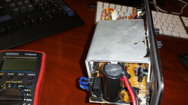
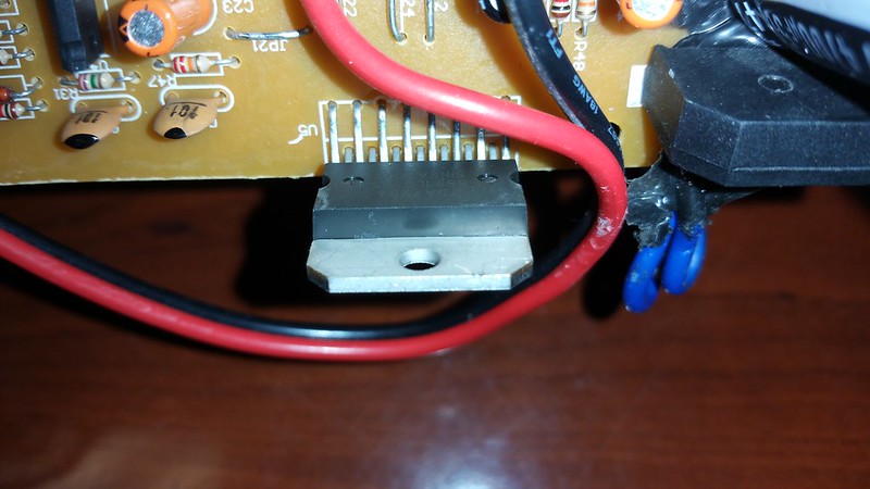
my assumption is the pin i circled in red is pin 1
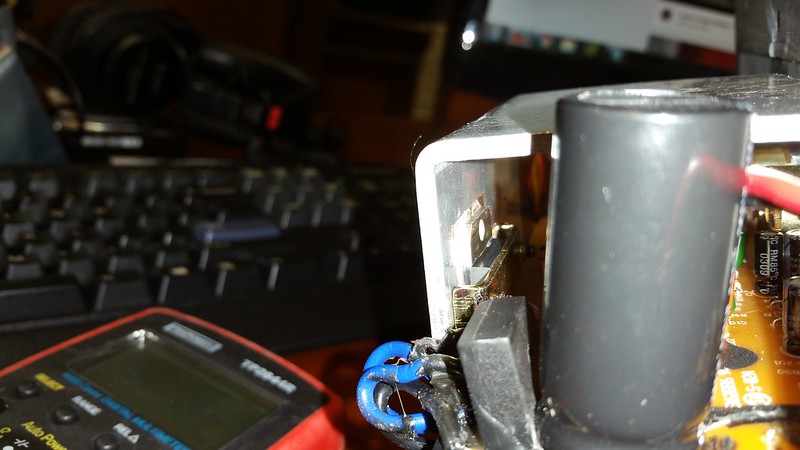
this is how the IC is coupled to the heatsink.
That heatsink connects to the plate amp itself. I'm not sure if it is grounded but i'm guessing it may be. There was a small piece of film between the IC and the heatsink from the factory. I left that intact. I also didn't have a load on the amplifier nor was I playing anything through it when I did the test. I dunno if that makes any difference. I just powered it on tested those pins you mentioned.
my assumption is the pin i circled in red is pin 1
this is how the IC is coupled to the heatsink.
That heatsink connects to the plate amp itself. I'm not sure if it is grounded but i'm guessing it may be. There was a small piece of film between the IC and the heatsink from the factory. I left that intact. I also didn't have a load on the amplifier nor was I playing anything through it when I did the test. I dunno if that makes any difference. I just powered it on tested those pins you mentioned.
I didn't test it because I didn't feel confident that I knew what I was doing to safely test it. I looked at the diagrams above and I don't know how to translate that to how this amp is designed. Specifically the supply circuit. I know it's silly but I wasn't sure if it was ok to power it all on without the ic soldered in. Either way it's been a little bit of a learning experience since this is the first time I've ever tinkered with any powered circuit.
I think I'm just gonna call it on this amp. I'm really far outta my depth and while I'm sure it's fixable, I don't understand how the circuits work so trying to diagnose why they aren't working correctly is a challenege. Thanks again for the time you guys put in on helping me.
We can't say you haven't tried ")
(That 'small piece of film' is an insulating washer that also has good heat transmission properties. So that was present. It is OK to power up without the IC, and its also OK to power up with no speaker which is the easy first option. You but your meter black lead on the main ground which is the junction of the two big caps, and then just check the supply voltage on the pins of the IC itself)
(That 'small piece of film' is an insulating washer that also has good heat transmission properties. So that was present. It is OK to power up without the IC, and its also OK to power up with no speaker which is the easy first option. You but your meter black lead on the main ground which is the junction of the two big caps, and then just check the supply voltage on the pins of the IC itself)
I know it's silly but I wasn't sure if it was ok to power it all on without the ic soldered in.
It is, and that would have led you to the problem.
I often use 9 volt batteries to power up for tests, if possible. Less likely to make magic smoke.
- Status
- This old topic is closed. If you want to reopen this topic, contact a moderator using the "Report Post" button.
- Home
- Amplifiers
- Chip Amps
- Help diagnosing bad subwoofer amp