It is more about maximising the capacitance available from that package size.
At least that is what H.Ott tells us.
Decide the package size that meets the tolerable inductance component, then select the highest capacitance.
An X7R of 2u2F, or 1uF, or 100nF, in that 1206 smd will have lower capacitance, than the 4u7F X7R in the same package.
At least that is what H.Ott tells us.
Decide the package size that meets the tolerable inductance component, then select the highest capacitance.
An X7R of 2u2F, or 1uF, or 100nF, in that 1206 smd will have lower capacitance, than the 4u7F X7R in the same package.
Message received.
So then going over to TDK's website and selecting the bias voltage (I chose 36V again) shows that a 10uF X5R beats the 4.7uF, not by much but looks to be a more optimum choice. 1.38uF for 4.7uF vs 1.65uF for the 10uF. Rather ironically the next best bet is a 3.3uF/100V X7S giving 1.54uF.
So then going over to TDK's website and selecting the bias voltage (I chose 36V again) shows that a 10uF X5R beats the 4.7uF, not by much but looks to be a more optimum choice. 1.38uF for 4.7uF vs 1.65uF for the 10uF. Rather ironically the next best bet is a 3.3uF/100V X7S giving 1.54uF.
Hi,
Thank's,
I had already read that article, but without understanding its advantage..
I will try this for my next amp, and see what's happen at listening.
If I go with 1000 uF electrolytic, I add 22 uF oscon and 4,7 uF ceramic
with 1500 uF, I will add 33 uF oscon and 6,8 uF ceramic
Right ?
Phil.
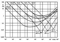
What Tom does is to look at the impedance of each capacitor in the supply.
In the graph you can see what the total impedance would be if you combined a 1000 uF electro and a 100nF ceramic.
Attachments
Can one buy 50V 4u7F X7R ceramic?
Bugger, just noticed that was for US stock, for which they add £15.95+VATthanks for that link.
Good price from a UK supplier.
4.5p+VAT for 50 off.
Whereas Digikey's price for 50off is > $147 and from my experience with Digikey bears no relation to the final at the doorstep charge.
The UK stocked cheapest is MC1206B475K500CT - MULTICOMP - SMD Multilayer Ceramic Capacitor, MC Series, 4.7 µF, ± 10%, X7R, 50 V, 1206 [3216 Metric] | Farnell element14
more than 5 times the price !
Why does Farnell do this?
Thank's Mark, little graph say more that a complete text bookIn the graph you can see what the total impedance would be if you combined a 1000 uF electro and a 100nF ceramic.
")
Phil.
Those graphs don't show the step in the phase response.
it's the sudden step that can give rise to ringing of paralleled capacitors.
The lower the esr the worse the risk of ringing.
Look how low some of the esr go. <5 to 10milli-ohms?
It's the esr that damps the ringing.
Does Y5V or X7S have good damping?
it's the sudden step that can give rise to ringing of paralleled capacitors.
The lower the esr the worse the risk of ringing.
Look how low some of the esr go. <5 to 10milli-ohms?
It's the esr that damps the ringing.
Does Y5V or X7S have good damping?
Last edited:
Actually...If implemented correctly, os-cons do provide some benefit. Measurement data here: LM3886 chip amp supply decoupling.
Mike
That is where I learned about these capacitors. I have not used them yet, but the datasheets encourage me.
Anyone that is considering building a chip amp should read this whole website. You don't have to build one of Tom's circuits (whose performance doesn't only depend on circuit design and component selection but also careful layout of the PC board), but you can glean simple tips to improve a simpler circuit.
Careful decoupling pays big benefits. Capacitor selection and physical proximity to the active device (lead length) makes a big difference. These are simple things that you can make happen yourself.
Last edited:
Those graphs don't show the step in the phase response.
it's the sudden step that can give rise to ringing of paralleled capacitors.
The lower the esr the worse the risk of ringing.
Look how low some of the esr go. <5 to 10milli-ohms?
It's the esr that damps the ringing.
Does Y5V or X7S have good damping?
That is true, Andrew. But these graphs are not the esr; they're the total impedance. And if the total impedance is so drastically low at high frequency, then that means that the resonance is significantly higher than the electrolytics alone (of course); not just that they exhibit lower esr than the electrolytics alone. And when the resonance is higher, then the phase response is better at higher frequencies.
And the esr of the capacitors does indeed improve the phase margin. If ringing is a problem, I might suggest using a high frequency resistor (like Vishay Dale CMF55 series) in series.
For the record, I use small ceramic capacitors soldered directly to the power supply chips on the bottom of the board. Then I use electrolytics of appropriate value for local bypass, as close to the chips as practical. Then I use big caps on the power supply board. I never have problems with ringing or resonance, but it could be because I haven't used these newer generation of capacitors yet and esr has saved me. I do intend to investigate some of them (like the os-con) soon. And I am astounded by that ceramic capacitor - when I learned about electronics, devices like this existed only in theory.
Andrew, the whole point of having a super low impedance bypass network is to have less interaction between the network and the chip. This increases linearity and also phase margin. If implemented correctly, it can improve transient response and overall stability. And phase margin at 10^7 or 10^8 Hz is hardly relevant; how much output voltage can these devices actually produce at these frequencies? Gain is way below 1 and Nyquist criteria is more than satisfied.
If I understand what others have told us, the value of impedance at the bottom of that impedance curve is actually resistance where the slope is zero.
That resistance is presumably esr.
The 10uF has a minimum impedance of under 5miili-ohms at the zero slope part.
The 1uF is under 10milli-ohms.
I believe following what I stated in para1 that these two values are esr of the respective capacitors.
That resistance is presumably esr.
The 10uF has a minimum impedance of under 5miili-ohms at the zero slope part.
The 1uF is under 10milli-ohms.
I believe following what I stated in para1 that these two values are esr of the respective capacitors.
I also understand your assembly description to be that which gives minimum risk of ringing if the supply rail gets a step change in current.....................For the record, I use small ceramic capacitors soldered directly to the power supply chips on the bottom of the board. Then I use electrolytics of appropriate value for local bypass, as close to the chips as practical. Then I use big caps on the power supply board. I never have problems with ringing or resonance, but it could be because I haven't used these newer generation of capacitors yet and esr has saved me. I do intend to investigate some of them (like the os-con) soon. And I am astounded by that ceramic capacitor - when I learned about electronics, devices like this existed only in theory.
If I understand what others have told us, the value of impedance at the bottom of that impedance curve is actually resistance where the slope is zero.
That resistance is presumably esr.
I think that this is theoretically true.
I also understand your assembly description to be that which gives minimum risk of ringing if the supply rail gets a step change in current.
It is how you get the maximum benefit from ordinary parts. It is an orthodox method among DIYers, and is better than some consumer grade equipment.
Your concerns are valid, Andrew. But the point is that we can benefit from these new generation of low esr, high resonance capacitors. Tom has done the research and presented the results, and I am encouraged.
"parallel" capacitor gets mentioned repeatedly on this Forum.
Many do not realise there is a good way to do it and a not so good way.
Agreed. In some applications, paralleling a high resonance capacitor will do no good and may introduce the potential for problems.
And I would like to point out that any electrolytic capacitor that would be in parallel with the os-con or low esr ceramic capacitor, close to it on the board, would have some significant esr that would dampen any ringing. In fact, you can make it that way.
I think that maybe that ceramic capacitor would be all you need for local bypass of an op amp. I don't like surface mount parts but I have used them and those could be soldered right on the back of a conventional board, right next to the chips.
If you carefully choose your capacitor values and physical placement, then you can keep the current flowing in one direction all the time.
Those capacitors seem very small. I would recommend 20,000uf per rail. Use two large 10,000uf per rail. Try to get low impedance computer grade capacitors and I would recommend a good make like like Panasonic, Elna, Sanyo, etc. You can leave the existing caps in their place. Just add the new caps after the bridge rectifier. Make sure the power wires or speaker wires are not too thin. Thin wires have a higher resistance which means they restrict current flow. The wires should be able to handle the full current rating of the amplifier with ease. Also keep all the wires as short as possible. Always make sure you are using 100nf disc ceramic capacitors after the bulk capacitors which are better at blocking off rf noise than the bigger capacitors. The disc ceramics should be as close to the IC legs as possible to be effective. Another thing to consider is a Zobel network.Hi All,
Just wanted to post a quick update and my impressions about this little amp I originally built around 2 years ago.
Initially, I thought it sounded so damn good. The mids and highs were crisp and clear. Vocals very lifelike. Bass, well I was also impressed with that too.
Over the lasts 2 years I have made a number of system upgrades and decided to have another listen today and hooked it up with my primary system. Which is as follows:
- Speakers: ProAc Studio 140MK2 (pic)
- Pre: Audiolab 8000S (pic)
- Power: Audiolab 8000P (pic)
- Dac: Musical Fidelity M1-DAC (Async 192) (pic)
- Source: Raspberry PI using Logitech Squeeze Player
For the LM3875 listening, I replaced the Audiolab 8000P - keeping the rest of the system as is.
I played Norah Jones "Cold Cold Heart" as the first track on the system. The vocals reminded me of why i loved this amp 2 years ago. VERY LIFE like. The crispiness and tone is very real. (sorry I am not an audio reviewer, so I am not sure about the right words that would convey my impressions).
After some critical listening I started to notice something missing and rather fatiguing. The soundstage is rather FLAT and un-involving compared to the Audiolab. The authority and grip Audiolab has over the low end is also lacking with this. Its almost someone has sucked the soundstage depth out of this system and replaced the 3D sound with a bad flattened replica. Something like someone replaced the marinara sauce with ketchup.
Not sure if the above makes any sense.
How do I go about improving the 3D soundstage and give this amp some balls?
Here are some pics of the build:
An externally hosted image should be here but it was not working when we last tested it.
An externally hosted image should be here but it was not working when we last tested it.
- Status
- This old topic is closed. If you want to reopen this topic, contact a moderator using the "Report Post" button.
- Home
- Amplifiers
- Chip Amps
- LM3875 - sound quality, soundstage and bass authority (2year reviewish)