Pawel. thanks for guidance.
My dc offset measure 30mv and 79 mv. Is this ok ?
I notice you mention 22k for the input pin to ground to lower output offset?
what value res do you have at the input?
try to put 100k potentiometer as input load, set it for the lowest offset and solder resistor that value.
I got with 100k input res the offset +70mV DC
with 18k I got -13mV
so my guess that 22k would give the lowest offset..
thanks thiagomogi for the suggestions .
What about raising the value of the resistor from speaker negative to ground? I have 0.5 R now.
No ... parallel with speaker ...... Take a look here .
https://www.passdiy.com/project/amp...e-amplifiers-and-sensitive-full-range-drivers
quote from Nelson Pass
"Let's assume that we want to achieve optimal frequency response for a given system. This is not necessarily the best-sounding system possible but causes less subjective arguments. We can trim the damping "Q" of the low frequency roll-off knee by trying different values for R0 (L0 = 0 in this case) until it flattens out to our taste. Most of the drivers we worked with were happy with values from about 22 ohms to about 47 ohms. It is surprising that so little damping gave such dramatic results but as previously pointed out, this category of loudspeaker responds well to small amounts of damping"
"Let's assume that we want to achieve optimal frequency response for a given system. This is not necessarily the best-sounding system possible but causes less subjective arguments. We can trim the damping "Q" of the low frequency roll-off knee by trying different values for R0 (L0 = 0 in this case) until it flattens out to our taste. Most of the drivers we worked with were happy with values from about 22 ohms to about 47 ohms. It is surprising that so little damping gave such dramatic results but as previously pointed out, this category of loudspeaker responds well to small amounts of damping"
I wrote about this, this amp has very high output impedance, so resonances in the speaker are not damped.
In the shown schematics, the output impedance is no more than 68 Ohm, the resistor value in parallel with the load.
Even with an infinite current source, the speaker main resonance is still somewhat mechanically damped.
I notice that the dc at the output depends on whether the speaker is connected
Without speaker connected, i measure about 1 v !
With speaker connected i get about 90 v and 110 mv .
This is still too high for my liking but i listen to the set for about 2 hrs already and the sound is very nice indeed,
I try changing the 12K input to ground resistor to 10K and 22 K and do not get much change in the dc offset at the output.
The amp is driven by a transistor buffer and the 100k volume control is in front of the buffer circuit.
Last edited:
If i will drive this amp directly from a Xonar U7 usb card, that outputs 1 Vrms (2.828 Vp-p), how many Watts will it produce? Or should i add a voltage amp before LM1875?
I need the full 20W output capability..
should last for 20W...
you will get 10A peak from 1V peak at the input when your speaker is 5 Ohm and current sensing resistor is 0.5 Ohm
I notice there is a thump on switching off the power , probably due to uneven capacitor discharge in the V+ and V- rails .
Is a speaker relay the only option?
I prefer the sound of this amp over a gainclone build with Peter daniel board.
It sound louder than the specs suggest and the bass is more tuneful .
Is a speaker relay the only option?
I prefer the sound of this amp over a gainclone build with Peter daniel board.
It sound louder than the specs suggest and the bass is more tuneful .
Is a speaker relay the only option?
I think so...
Is 4700uF/rail enough as power supply filter for this amp?
yes, I used only 3300uF
but better supply = better sound
Would this amp be OK and not destroy my Selenium D220ti drivers directly connected, without any condensator or resistor? The driver has Re=6 ohm and will be actively crossed LR4 @ 1450Hz.
I ordered a 150VA toroidal transformer.
If i use it for both L and R, each channel with its own rectifier and filter, could it be a problem?
I ordered a 150VA toroidal transformer.
If i use it for both L and R, each channel with its own rectifier and filter, could it be a problem?
Would this amp be OK and not destroy my Selenium D220ti drivers directly connected, without any condensator or resistor? The driver has Re=6 ohm and will be actively crossed LR4 @ 1450Hz.
I ordered a 150VA toroidal transformer.
If i use it for both L and R, each channel with its own rectifier and filter, could it be a problem?
in general should not be a problem, please follow general rules from Joe's thread: http://www.diyaudio.com/forums/chip...-watt-transconductance-current-amplifier.html
an interesting application
I’ve found on this old book: Linear and Interface Circuit Application Volume 1 (Texas Instruments 1986) an intersting circuit tuned to this thread, with a very exhaustive and complete description. (why the semiconductor-companies don't make any more these nice applications gifts?)
"Most audio amplifier circuits today are voltage output devices which apply a voltage to the terminals of the speaker. Large changes in speaker impedance with frequency yield poor frequency response with the high-frequency output falling off rapidly as the speaker impedance increases. It should be noted that the speaker cone displacement is proportional to the current in the voice coil rather than the voltage across the speaker terminals. The current is the primary mover of the voice coil.
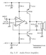
The single speaker amplifier circuit shown in Figure 3-31 uses current feedback rather than the more popular voltage feedback. As shown, the feedback loop is from the junction of the speaker terminal and a 0.5Ω resistor, to the inverting input of the NE5534. Sensing the current through the speaker and feeding it back provides better speaker damping than obtainable with voltage-drive systems.
Note the unusual grounded output pin on the NE5534 op-amp. When the input to the amplifier is positive, the power supply supplies current through the TIP32 and the load to ground. Conversely, with a negative input the TIP31 supplies current through the load to ground. The gain in this case is set to about 15 (gain = SPKR 8Ω / 0.5Ω feedback). The 0.22µF capacitor across the speaker rolls off its response beyond the frequencies of interest. Using the 0.22µF capacitor specified, the amplifier output is 3 dB down at 90kHz where the speaker impedance is about 20Ω. The Quiescent output stage collector current is determined by the 130 Ω resistors that connect each transistor base to the appropriate supply rail, the output transistor VBE, and the 1Ω emitter resistors. To set the recommended class 'A' output collector current, adjust the value of either 130Ω resistor. An output current of 50 to 100mA will provide a good operating midpoint between the best crossover distortion and power dissipation.
The 0.1 µF bypass capacitors on each rail may be mylar or ceramic disk. The 2.0 µF should be a nonpolarized capacitor while the 0.22µF across the speaker should be mylar.
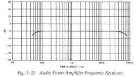
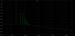
Figure 3-32 shows the frequency response of the amplifier with a 2.0µF input capacitor. This response is very flat with the -3.0dB point on the low frequency end at 45 Hz. The -3.0dB point at the high frequency end occurs at 80kHz. Total Harmonic Distortion (THD) is 0.01% at 6.25W rms output into an 8 Ω load with ±18V on the supply rails."
I’ve found on this old book: Linear and Interface Circuit Application Volume 1 (Texas Instruments 1986) an intersting circuit tuned to this thread, with a very exhaustive and complete description. (why the semiconductor-companies don't make any more these nice applications gifts?)
"Most audio amplifier circuits today are voltage output devices which apply a voltage to the terminals of the speaker. Large changes in speaker impedance with frequency yield poor frequency response with the high-frequency output falling off rapidly as the speaker impedance increases. It should be noted that the speaker cone displacement is proportional to the current in the voice coil rather than the voltage across the speaker terminals. The current is the primary mover of the voice coil.
The single speaker amplifier circuit shown in Figure 3-31 uses current feedback rather than the more popular voltage feedback. As shown, the feedback loop is from the junction of the speaker terminal and a 0.5Ω resistor, to the inverting input of the NE5534. Sensing the current through the speaker and feeding it back provides better speaker damping than obtainable with voltage-drive systems.
Note the unusual grounded output pin on the NE5534 op-amp. When the input to the amplifier is positive, the power supply supplies current through the TIP32 and the load to ground. Conversely, with a negative input the TIP31 supplies current through the load to ground. The gain in this case is set to about 15 (gain = SPKR 8Ω / 0.5Ω feedback). The 0.22µF capacitor across the speaker rolls off its response beyond the frequencies of interest. Using the 0.22µF capacitor specified, the amplifier output is 3 dB down at 90kHz where the speaker impedance is about 20Ω. The Quiescent output stage collector current is determined by the 130 Ω resistors that connect each transistor base to the appropriate supply rail, the output transistor VBE, and the 1Ω emitter resistors. To set the recommended class 'A' output collector current, adjust the value of either 130Ω resistor. An output current of 50 to 100mA will provide a good operating midpoint between the best crossover distortion and power dissipation.
The 0.1 µF bypass capacitors on each rail may be mylar or ceramic disk. The 2.0 µF should be a nonpolarized capacitor while the 0.22µF across the speaker should be mylar.
Figure 3-32 shows the frequency response of the amplifier with a 2.0µF input capacitor. This response is very flat with the -3.0dB point on the low frequency end at 45 Hz. The -3.0dB point at the high frequency end occurs at 80kHz. Total Harmonic Distortion (THD) is 0.01% at 6.25W rms output into an 8 Ω load with ±18V on the supply rails."
Attachments
I’ve found on this old book: Linear and Interface Circuit Application Volume 1 (Texas Instruments 1986) an intersting circuit tuned to this thread, with a very exhaustive and complete description. (why the semiconductor-companies don't make any more these nice applications gifts?)
"Most audio amplifier circuits today are voltage output devices which apply a voltage to the terminals of the speaker. Large changes in speaker impedance with frequency yield poor frequency response with the high-frequency output falling off rapidly as the speaker impedance increases. It should be noted that the speaker cone displacement is proportional to the current in the voice coil rather than the voltage across the speaker terminals. The current is the primary mover of the voice coil.
The single speaker amplifier circuit shown in Figure 3-31 uses current feedback rather than the more popular voltage feedback. As shown, the feedback loop is from the junction of the speaker terminal and a 0.5Ω resistor, to the inverting input of the NE5534. Sensing the current through the speaker and feeding it back provides better speaker damping than obtainable with voltage-drive systems.
Note the unusual grounded output pin on the NE5534 op-amp. When the input to the amplifier is positive, the power supply supplies current through the TIP32 and the load to ground. Conversely, with a negative input the TIP31 supplies current through the load to ground. The gain in this case is set to about 15 (gain = SPKR 8Ω / 0.5Ω feedback). The 0.22µF capacitor across the speaker rolls off its response beyond the frequencies of interest. Using the 0.22µF capacitor specified, the amplifier output is 3 dB down at 90kHz where the speaker impedance is about 20Ω. The Quiescent output stage collector current is determined by the 130 Ω resistors that connect each transistor base to the appropriate supply rail, the output transistor VBE, and the 1Ω emitter resistors. To set the recommended class 'A' output collector current, adjust the value of either 130Ω resistor. An output current of 50 to 100mA will provide a good operating midpoint between the best crossover distortion and power dissipation.
The 0.1 µF bypass capacitors on each rail may be mylar or ceramic disk. The 2.0 µF should be a nonpolarized capacitor while the 0.22µF across the speaker should be mylar.
Figure 3-32 shows the frequency response of the amplifier with a 2.0µF input capacitor. This response is very flat with the -3.0dB point on the low frequency end at 45 Hz. The -3.0dB point at the high frequency end occurs at 80kHz. Total Harmonic Distortion (THD) is 0.01% at 6.25W rms output into an 8 Ω load with ±18V on the supply rails."
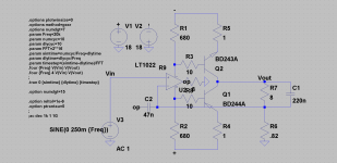
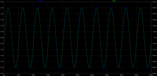
very fine proposition, I simmed this topology but is seems that is very prone for the oscillation.
I had to tammed LT1022 with 47n cap!
People who built this agreed the same.
Attachments
Thanks, padamiecki,
Do you know if even with NE5534 OpAmp and Tip31-32 transistors the circuit transforms itself into an oscillator? I think it's worth the effort to try it, because at that time (1986) serious companies with a prestigious name (as TI) tested the circuits before publishing.
Regards. Luigi
Do you know if even with NE5534 OpAmp and Tip31-32 transistors the circuit transforms itself into an oscillator? I think it's worth the effort to try it, because at that time (1986) serious companies with a prestigious name (as TI) tested the circuits before publishing.
Regards. Luigi
- Status
- This old topic is closed. If you want to reopen this topic, contact a moderator using the "Report Post" button.
- Home
- Amplifiers
- Chip Amps
- LM1875 transconductance amp