G'day. This is my first post here in the chip amps section, so hi.
As well as my stAMPs, I also use an LM3886 amp for normal listening. I've used the LM3886 in the standard (datasheet) config, then I built a myref-ish thing using the LME49720 and a DC servo. If you're wondering why I'm using the LME49720 as opposed to the LME49710, it's because I use the other half as the integrator for the DC servo. Yes it doesn't have the same level of DC accuracy as an OPA227 for example, but that is totally unnecessary for a power amp IMO.
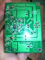
I was making a PCB order a few weeks ago and had some space left, so I whipped this amp and PCB up in a morning. It's not perfect but it definitely sounds like a notable improvement over either my myref-ish thing and definitely better than the standard LM3886. PCB size is 1.75"x1.75", and the ground plane is split in two places so there is a star ground at the LM3886 ground pin. I left spaces on the PCB for extra compensation related components so that it can be fiddled with and improved. I've attached schematics and a couple pictures of the PCB (note that some decoupling caps are missing from the schematic).
Oh and this isn't a copy of anything. I thought I should mention in case someone thought I had ripped off the Modulus-86 or something, which I haven't.
As for performance, the distortion at 15W RMS, 1KHz into 8 ohms was less than my sound card could measure, which is 0.0003%. I'll get some more graphs and upload them. Of course, distortion levels this low are trivial. DC offset on the output is about 500uV, but it does need about 200mS to settle so I have a relay delay output thingy. Please feel free to take the design and figure out some better values for things, I would do it myself but I don't have the time at the moment.
Anyway, any suggestions/comments/criticisms?
As well as my stAMPs, I also use an LM3886 amp for normal listening. I've used the LM3886 in the standard (datasheet) config, then I built a myref-ish thing using the LME49720 and a DC servo. If you're wondering why I'm using the LME49720 as opposed to the LME49710, it's because I use the other half as the integrator for the DC servo. Yes it doesn't have the same level of DC accuracy as an OPA227 for example, but that is totally unnecessary for a power amp IMO.
I was making a PCB order a few weeks ago and had some space left, so I whipped this amp and PCB up in a morning. It's not perfect but it definitely sounds like a notable improvement over either my myref-ish thing and definitely better than the standard LM3886. PCB size is 1.75"x1.75", and the ground plane is split in two places so there is a star ground at the LM3886 ground pin. I left spaces on the PCB for extra compensation related components so that it can be fiddled with and improved. I've attached schematics and a couple pictures of the PCB (note that some decoupling caps are missing from the schematic).
Oh and this isn't a copy of anything. I thought I should mention in case someone thought I had ripped off the Modulus-86 or something, which I haven't.
As for performance, the distortion at 15W RMS, 1KHz into 8 ohms was less than my sound card could measure, which is 0.0003%. I'll get some more graphs and upload them. Of course, distortion levels this low are trivial. DC offset on the output is about 500uV, but it does need about 200mS to settle so I have a relay delay output thingy. Please feel free to take the design and figure out some better values for things, I would do it myself but I don't have the time at the moment.
Anyway, any suggestions/comments/criticisms?
Attachments
![IMG_20150110_120547[1].jpg](/community/data/attachments/413/413590-4fc3d2b04d896967af791e0b534d8ec3.jpg)
... and the ground plane is split in two places so there is a star ground at the LM3886 ground pin. ...
The chip gnd pin is just for the mute circuit, so it doesn't deserve to be 'star' of anything
")
Speaking of 'stars', looks like the actual data's pointing more towards low-impedance grd plane, especially with a fast controlling opamp. But I'll let the pros explain it.
Watch for power-handling issues with small smt parts ... especially Rf since it gets the full swing of the output, I think it's in the SMTLM3886 thread.
Love your stuff by the way, gotta try me 'un of yer cuuuuuuute stamps!
Cheers,
Jeff
The chip gnd pin is just for the mute circuit, so it doesn't deserve to be 'star' of anything
Speaking of 'stars', looks like the actual data's pointing more towards low-impedance grd plane, especially with a fast controlling opamp. But I'll let the pros explain it.
Watch for power-handling issues with small smt parts ... especially Rf since it gets the full swing of the output, I think it's in the SMTLM3886 thread.
Love your stuff by the way, gotta try me 'un of yer cuuuuuuute stamps!
Cheers,
Jeff
Yes, I read something about that on Tom's (I forget his last name) page on the LM3886. As I say, there's a lot of room for improvement here.
The low resistance of Rf etc is fine as I only operate this amp on +/-20V and I don't listen to things very loud. Those values could be simply doubled anyway.
How about going over to TL431 shunts in place of the LM317/337s? Reason being the regs you have give a surprisingly high Zout at low output currents. Shunt regs also aren't limited to as low an input-output voltage as the LM regs so punters who like it loud can go louder.
TL431 seems a bit OTT - I've built 0.05% references with a TL431 before.
But yes, a zener shunt makes sense. If I build another set of boards then I'll incorporate this, thanks for the tip.
The cooking grade TL431s are about 2% I seem to recall and under half the price of a TO220 reg. Yes they make accurate ones but I'm not suggesting those. Don't use the Chinese (Hong Kong, 'WS') brand though as they're way too noisy.
Yes - of course. I forgot that there were different grades.
Since the psrr of the lme49720 is really good and it will correct all, does regulator is really needed ?
I just finished soldering of a Bato MM board - composite bridged lme49720/lm3886 with trim offset, remote sensing, and a lot of decoupling onboard, so i'm really interested in your project.
I just finished soldering of a Bato MM board - composite bridged lme49720/lm3886 with trim offset, remote sensing, and a lot of decoupling onboard, so i'm really interested in your project.
Last edited:
That's a good point, these ultra low noise regs are not exactly necessary. The opamp designers have worked on high PSRR so that you don't have to worry so much about the supply...
I've not seen the Bato MM board until now. It seems there is a lot more about these composite amps around than I realised. I really like the idea of having a sense line to the speaker. I've joined diysmps so I can read a bit more about it.
I've not seen the Bato MM board until now. It seems there is a lot more about these composite amps around than I realised. I really like the idea of having a sense line to the speaker. I've joined diysmps so I can read a bit more about it.
The full version original thread need to be translated from here, but it s a lot more technical : Bato MM-Amp (LM-most by macolakg) : Dokumentacija It seems that the original forum gone down and all was copied on yu3ma s forum. V1 smd pcb is very cool...
Last edited:
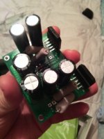
wanted to go fast so not really clean soldering and made order errors...but here is mine. Not yet tested. I got 9 more board, will keep 5 so 4 left if you want to try one...
From upside view, we do not see stacked smd decoupling cap neither crappy serial cap to get votage ratings bellow big solder point
From upside view, we do not see stacked smd decoupling cap neither crappy serial cap to get votage ratings bellow big solder point
Attachments
Last edited:
That's a good point, these ultra low noise regs are not exactly necessary. The opamp designers have worked on high PSRR so that you don't have to worry so much about the supply...
@papasteack: Some kind of reg's needed so that the opamp's supply voltage specs aren't exceeded. The 3886 can handle a lot more volts than the 49720. These chips do only have good PSRR at lower frequencies though.
If THD is the overriding concern then to achieve lowest THD in-situ (with a real speaker load) sense lines become mandatory. Otherwise you'll only get your headline 3-zeros-after-the-decimal number with a purely resistive load.I've not seen the Bato MM board until now. It seems there is a lot more about these composite amps around than I realised. I really like the idea of having a sense line to the speaker. I've joined diysmps so I can read a bit more about it.
These chips do only have good PSRR at lower frequencies though.
So does lm338 kind reg. Don't know about shunt regs for the moment with my limited knowledge; it seems pretty interesting, but there's too much different implementation on the web, and don't know where to start trying to make my opinion.
Why not good reg (shunt?) only for the lme49720 (and not for the lm3886), or since it doesn't need high power, a simple filter for it ( crcrc for example + good decoupling of course) ?
Various discrete shunt regs exist but for an opamp methinks they're overkill. TL431s I love because they're seriously cheap - the output impedance at lower freqs is around 0.2ohms. They only need less than 1mA quiescent current so well suited to loads in the single digit mA range. Line regulation might be an issue - if so it can be improved substantially by using an LM317L as a CCS to feed them.
@papasteack: Some kind of reg's needed so that the opamp's supply voltage specs aren't exceeded. The 3886 can handle a lot more volts than the 49720. These chips do only have good PSRR at lower frequencies though.
I meant that the LM317/337 is good enough (shunt regs not needed). I have a box full of LM317/337 so it's not an issue for me.
If THD is the overriding concern then to achieve lowest THD in-situ (with a real speaker load) sense lines become mandatory. Otherwise you'll only get your headline 3-zeros-after-the-decimal number with a purely resistive load.
Of course, low THD like this is trivial (as I said in the OP). Sense lines to the speaker are a very good idea though - this board could quite easily be modded for this.
I have a hard time believing the circuit in the pdf is stable with the given component values at least by quick eyeball and counting on my thumbs look at gains, time constants
I would say the same thing. But it is stable and works fine, or I wouldn't have published it.
I would have posted measurements but my function gen is currently being repaired.
As I said before, the values are probably not optimal as it was designed in a morning.
I drew up the basic circuit and gave the values an educated guess, then built it point-point and adjusted the compensation until I had a nice crisp square wave up to 20KHz.
In addition to what I said above, I will provide more measurements when my function gen is fixed. My HP 34401A has also developed a fault on the ohms range so I might be busy for a while...
If you're wondering why I'm using the LME49720 as opposed to the LME49710, it's because I use the other half as the integrator for the DC servo. Yes it doesn't have the same level of DC accuracy as an OPA227 for example, but that is totally unnecessary for a power amp IMO.
You may want to redo the math on that one... I doubt you get much benefit of the DC servo in terms of output offset unless you use an op-amp with low input voltage offset and low input bias current.
Oh and this isn't a copy of anything. I thought I should mention in case someone thought I had ripped off the Modulus-86 or something, which I haven't.
I'm not worried about competition...
While your circuit uses a composite topology, it's pretty far from the Modulus-86, actually.As for performance, the distortion at 15W RMS, 1KHz into 8 ohms was less than my sound card could measure, which is 0.0003%.
Try measuring at 20 kHz. That'll tell you a lot about the performance of the layout as well as the amount of loop gain available at 20 kHz.
Also look at the THD at 20 Hz. That's where any THD from the DC servo will show up.
I'll get some more graphs and upload them. Of course, distortion levels this low are trivial.
I'm guessing you dropped the 'not'. As in "not trivial".
Anyway, any suggestions/comments/criticisms?
Neat circuit. I like the form factor. There's room for improvement in the supply routing, it seems. I also suggest adding the Zobel and Thiele networks so your circuit will remain stable with a slightly capacitive load.
Have you looked at the performance as the output voltage reaches the rail. That's where trouble brews a lot of the time. I suggest testing both with a square wave and with a sine wave. Slowly increase the amplitude of the input signal until the amp clips and go a bit beyond clipping. Watch the output on an oscilloscope. It's common with oscillation in that region of operation and I suggest finding a solution for it...
~Tom
Last edited:
You may want to redo the math on that one... I doubt you get much benefit of the DC servo in terms of output offset unless you use an op-amp with low input voltage offset and low input bias current.
I'm not worried about competition...
Try measuring at 20 kHz. That'll tell you a lot about the performance of the layout as well as the amount of loop gain available at 20 kHz.
I'm guessing you dropped the 'not'. As in "not trivial".
Neat circuit. I like the form factor. There's room for improvement in the supply routing, it seems. I also suggest adding the Zobel and Thiele networks so your circuit will remain stable with a slightly capacitive load.
Have you looked at the performance as the output voltage reaches the rail. That's where trouble brews a lot of the time. I suggest testing both with a square wave and with a sine wave. Slowly increase the amplitude of the input signal until the amp clips and go a bit beyond clipping. Watch the output on an oscilloscope. It's common with oscillation in that region of operation and I suggest finding a solution for it...
~Tom
I was hoping you'd turn up
(no sarcasm)The input biasing current of the LME49720 is 10nA and the offset voltage is 100uV, (typical datasheet values) so not ideal for a DC servo application. But IMO it's "good enough", and it turns what would otherwise be an offset of up to several hundred mV into an offset below 1mV. Also board space is a problem for two opamps, and cost if I wanted a decent FET opamp.
As for the distortion, I would measure it at 20KHz but my sound card oddly won't measure anything above about 10KHz, it just drops off after that. That's only the standard motherboard line in though, I really need to build something better for making measurements.
As for the distortion values, I do personally believe that the difference between 0.03 and 0.0003% THD is not audible. I do however believe that the side effects of the lower distortion is what makes the difference - from the quick measurements that I have done, the fast opamp keeps the LM3886 "in check" at higher volumes where it might otherwise distort a bit. But that's my opinion.
There is certainly room for improvement on the board, although the supply routing seems OK to me (?).
I'll give the boards some more rigorous testing when my function generator is working again, as I said before. I suspect that only so much can be done with this topology though, it's quite simple compared to most of the ones that I see.
- Status
- This old topic is closed. If you want to reopen this topic, contact a moderator using the "Report Post" button.
- Home
- Amplifiers
- Chip Amps
- LM3886 & LME49720 composite amp