Now I need a preamp, any recommendations for a good one. I prefer differential outputs of course.
Less than $1000.
My Universal Buffer would set you back $149 + power supply, volume control, and chassis.
I expect to have a power supply and input selector available for it within the next few months.
Tom
Tom I'm running a pair of parallel 86 boards as a bridged monoblock chassis.
The reason I ask is because I want to use a Stax energize that cant take a bridged input.
You cannot connect any of the outputs of a bridged amp to ground. That would short out that half of the amp.
Instead, I would bring out both the Speaker GND and Speaker (+) terminals for the two amp halves. Connect the speaker to the two (+) terminals for bridged mode and to the GND and (+) for non-bridged mode. You can connect the Stax between GND and (+) then.
Tom
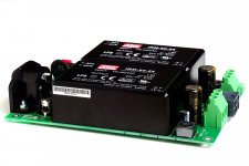
Those of you who are on the fence about the SMPS-86 might consider getting off the fence and onto the internet. I have three boards left and will likely not make more of them. It's a pretty slow seller and there are many more SMPS options available now than when I designed the circuit.
The SMPS-86 is an excellent candidate for a desktop LM3886-based amp, such as the Modulus-86. With that supply, an LM3886-based amp will deliver 28 W into 8 Ω and 28 W into 4 Ω. However, due to the current limit of the switching power supplies used on the SMPS-86, you will only get 2x14 W into 4 Ω if you build a stereo amp.
Thus, the SMPS-86 is mostly suited for mono blocks, for amps driving 8 Ω speakers, and desktop amps.
The SMPS-86 provides ±24 V @ ±2.5 A by default. It can be built for ±5 V (±10 A), ±12 V (±5 A), and ±15 V (± 4 A) as well. Many use it to power preamps and it would be an excellent, albeit a bit overkill, power supply for my Universal Buffer.
To see the current stock levels, please see my website. The current stock is indicated just below the price.
Tom
Attachments
Last edited:
Interesting with the image width. A few days ago I received a 4-conductor, 50' SpeakON cable (GLS brand via Amazon). My plan is to cut it in half and use it to bi-amp my KEF R700 using the Modulus-686. If I experience any changes in imaging, I'll let you know.
Bi-amping rocks. Granted this is a sighted N = 1 trial, so the usual biases and error sources apply. Still. The imaging is much improved. Is it night vs day? Probably not... But slightly fuzzy holographic versus amazingly holographic is worth taking.
")
My setup: MacBook Pro (2010) -> Optical link -> RME ADI-2 DAC FS -> 2x Modulus-686 -> KEF R700. I'm using the differential outputs of the DAC, of course. Just add XLR Y cables to drive two amplifier inputs from one output.
Tom
The panels were soaked in cutting oil and the four posts connecting the corners hadn't been de-burred. The tolerances were OK and the chassis came together pretty nicely. I would say the surface finish was OK, but nothing spectacular. My chassis was the "BZ4309".
Tom
I used the BZ4309 chassis in my build of two Mod 86, two Parallel 86, two Power 86 and a transformer and the chassis I received was fine as far as quality and cleanliness was concerned...YMMV!
bi amping
hi tom
i seem to remember you were using the mark audio 10p drivers have you switched full time to kef? and were their any trade offs?
i am also planning to bi amp i have 2 mod86v2.2 for bass and planning 2x mod86v2.4 for tweeters will their be a mismatch between amp updates
hi tom
i seem to remember you were using the mark audio 10p drivers have you switched full time to kef? and were their any trade offs?
i am also planning to bi amp i have 2 mod86v2.2 for bass and planning 2x mod86v2.4 for tweeters will their be a mismatch between amp updates
I've never used the MA Alpair 10P. I have a pair of bookshelf speakers based on the Alpair 6P that I use in my office/lab.
In my main system, I went from KRK R6 (passive) to LXmini to KEF R700. I have a pair of Dali 3A that I pull out for testing on occasion as well.
As you can see in the revision history that I posted a few days ago, there were only minimal changes from Rev. 2.0 to 2.4. The changes around Rev. 2.0-2.3 dealt with TI's decision to discontinue, then revive, then discontinue for good the LME49710. Rev. 2.3 uses the LME40720. It also improved the EMI filter and changed the output inductor to the 1.1 uH that I had custom wound. All these changes affect the performance above 1 MHz. They had no impact within the audio band. The current revision, rev. 2.4, uses the LME49720 as well. All parts in Rev. 2.4 are in current production.
Tom
Last edited:
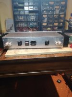
Changed to balanced and added a power switch!!! It's quieter. I really blew the initial wiring, but somehow it worked. This is better -- I'll try it in a full range system later this week, but for now, it's on the experimental system doing horn duty.
Attachments
I too just stuffed the wire in.
Tom, I have a question. It's basic....In the docs I have, the power86 shows two ground points.
I've used only one -- the one on the DC connector. This is wired to a lug that is shared by safety earth.
Is this correct or should I also wire the AC ground connector? If I should wire it, should I also bring that to the safety earth lug.
AC mains inlet ground pin goes directly to the chassis. Sand off the anodizing and preferably use a grounding lug with 'teeth'. I recommend using a lock nut on the mounting screw for the grounding lug to prevent it from coming loose.
Then connect a wire from the grounding lug to the ground output of the supply.
Tom
Then connect a wire from the grounding lug to the ground output of the supply.
Tom
AC mains inlet ground pin goes directly to the chassis. Sand off the anodizing and preferably use a grounding lug with 'teeth'. I recommend using a lock nut on the mounting screw for the grounding lug to prevent it from coming loose.
Then connect a wire from the grounding lug to the ground output of the supply.
Tom
Exactly what I did, except there was no anodizing to worry about.
My concern was solely due to the added gnd symbol on the version 1 drawings I have.
Thanks for clearing that up.
If I build an amp around the SMPS300RE, do I still need to use a fuse in (or around) the IEC outlet or the one built-in is enough?
Also, what kind of quick disconnects / faston connectors should I use for the SMPS out pins? Any 4.8 mm one + a heat shrink tube, or one of those pre-insulated ones?
Also, what kind of quick disconnects / faston connectors should I use for the SMPS out pins? Any 4.8 mm one + a heat shrink tube, or one of those pre-insulated ones?
If you add a fused IEC inlet, the fuse will protect everything in the chassis (assuming the fuse is sized correctly). If you rely solely on the fuse on the SMPS, you don't have any protection in case the mains wire comes loose from the SMPS and drops onto the chassis or if the mains switch shorts out. So I'd recommend using a fused inlet.
The QC terminals are 6.3 x 0.81 mm.
Tom
The QC terminals are 6.3 x 0.81 mm.
Tom
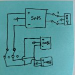
I would like to add a front switch to my build I am using the SMPD-86 power supply. Could I wire a DPDT switch between the power supply and amp boards like illustrated in the attached drawing? The switch I want to use is rated at 3A 250V AC.https://www.digikey.com/product-detail/en/e-switch/ULV4F2GSS341/EG5190-ND/5299300
Attachments
If you need an always-on standby voltage for anything, I'd get one of the small AC/DC switchers (IRM-02-xx, for example).
Tom
Simpler than that. Just looking for the best way to have a front mounted power switch since where the amp is going it will be difficult to use a rear mounted one.
The simplest way is to connect a mains voltage rated switch where the PCB-mounted one would be.
Tom
Will that switch I linked above do the job? Note it's only rated at 3A while the one you spec is rated at 5A. Overall though the SMPS puts out 2.5A correct?
- Home
- Amplifiers
- Chip Amps
- Modulus-86 build thread