im happy to do all the smd if it means keeping the price down a bare board option would be fantastic
If you're willing to buy 1000 boards, I'll be happy to provide an all-SMD build for you specifically.
")
I know that many here are perfectly comfortable and competent soldering SMD components. However, I also know from past experience, that even the most competent and experienced builder makes the occasional mistake, and that the number of mistakes increases dramatically with SMD builds. It's just too easy to miss a solder joint, make a cold solder joint, or apply too much heat resulting in cracked components with SMD. Such mistakes lead to a bad build experience, stressful support calls, and loss of business.
I'm obviously expecting to have to support my circuits. That's one of the things I provide that you don't get in many other places. However, at the relatively low prices I charge, I need the vast majority of builds to be successful, and need to be able to resolve the few resulting support cases in a few emails. Sadly all-SMD DIY builds are not conducive to this, thus, I cannot support all-SMD DIY builds.
There are other good business reasons for why I won't support all-SMD DIY builds. I cover quite a few of them in Post 4579.
Tom
Questions about parts/component selection
Hi,
Newbie here. Just bought 4 Mod86 boards and a Power686 board for building 4 channels Mod86 Amp. While waiting for the boards to arrive, I has been studying the building manuals and BOM. About the BOM, I have some questions on the parts/component selection:
1. Use of Ceramic Capacitors
I note that some or most of the by-pass capacitors are Ceramic Capacitors. Any reason of choosing Ceramic over normal film cap? Understand that Ceramic Cap may cost lower but the standard film cap with the same rating and voltage are not that more expensive. I believe film cap can is more stable with better performance. Can I use film cap instead of Ceramic cap?
2. Replacing some Capacitors by Elna Silmic II
Not sure if this can improve performance but I like to use Elna Silmic II instead of Nichicon/Panasonic. Also, I prefer tinned copper wire of Elna to tinned steel wire of Nichicon/Panasonic. Is there any issue if I use Elan Silmic II with the same capacitance and same or higher voltage rating? I will not replace those with special spec such as extra low impedance.
3. Using Dale resistors
Just curious the choice of KOA over Dale. Not sure if KOA use steel wire but Dale definite uses copper wire. I may also like to use higher wattage and lower PPM series which is my preference. They may cost a bit more but the total increment in cost could be minimal.
I understand that Tom has selected the parts basing on specification, measurement, availability and price. Therefore, I would like confirm such change/alternative will not jeopardise the amp performance before ordering them.
In addition, if I don't need to swap transforms of boards, is it more appropriate to solder the wire direct to the boards instead of using connectors?
Also, I will double check the size of the proposed alternative can properly fit to board. I already note that the Elan Silmic may be a bit larger than the Nichicon/Panasonic with similar spec, and the resistors with higher wattage rating should be a bit larger.
Would like to have your opinion on the above.
Thanks.
By substituting parts you will probably make things worse, not better. I bet BOM is carefully choosen and provided measurments comfirms that.
Ceramic capacitors are best choice in local supply bypassing. They offer very low ESR, ESL and high capacity in small sizes. Importance of proper supply decoupling is discussed here - LM3886 chip amp supply decoupling.
Same with Elna Silmic II - they don't even specify ESR in datasheet and are rated just for 85*C. It might be hard to fit them to existing outline. They tend to be much bigger than other capacitors with same capatiance/voltage ratings.
Any thin film resistor from reputable manufacturer would be ok.I don't think that few mm of steel vs copper lead would make any diffrence. KOA, Dale, Beyschlag or Yageo will be equally good.
when I built my parallel 86 amps I had some questions too, Tom told me that modifying the BOM will not help at all, but you could play with some of the components.
Decoupling electrolytic caps are nichicon PW(105 C) , but panasonic FR,FC or FS (and other) are very good too for that matter. But I would not use Elna ...
Ceramic capacitors in the BOM are X7R for the large values (1uf or more) and c0g for the rest of them . Ceramic caps are small in size and the c0g caps are very very good. Plastic caps are good too but they are a little bit larger in size.
Dale resistors are fine , but they are a little expensive and I don't think you will be able to hear any difference . mrs25 , mbb0207 are popular series .
You could solder the wires directly to the board , but trust me on this one, you will connect and disconnect the boards many times before you have them in a enclosure .
I guess when you will buy stuff is better to buy from ONE place so you will avoid paying multiple shipping charges .
Have fun!
The two previous responses say pretty much all I wanted to say (thanks!!). I'll add a little explanation here.
You're unlikely to find a film cap that outperforms an X7R/X8R ceramic cap. Film caps probably have lower voltage coefficient, but I selected the caps such that the voltage coefficient of the ceramic is not an issue.
C0G/NP0 is the best ceramic available. To the best of my knowledge, it outperforms mica and such in the capacitance ranges used in the Modulus series.
I respect your preference. Just beware that the electrons won't care.
Electrons do care about added inductance, however. You'll likely create more harm than good by shoehorning in a physically larger cap into the PCB.
Go for it. It won't make a bit of difference, but if you like Dale better than KOA, have at it. Electrons are not that brand loyal, it turns out...
I tend to derate resistors 4-5x on power, so power dissipation should be the least of your worries. Lower temperature coefficient and lower voltage coefficient are good things, though, if I could get better performance by selecting lower TC or lower VC components, I would have done so.
I don't have the schematic with me (I'm on vacation), so I don't have the component reference handy. If I recall correctly, it's R12 that's worth geeking out about. 20.0 kΩ. You want a low TC, low VC resistor there.
You can solder directly if you wish. It's just vastly more convenient to use the connectors. The performance measurements I've performed were performed with connectors.
Tom
1. Use of Ceramic Capacitors
You're unlikely to find a film cap that outperforms an X7R/X8R ceramic cap. Film caps probably have lower voltage coefficient, but I selected the caps such that the voltage coefficient of the ceramic is not an issue.
C0G/NP0 is the best ceramic available. To the best of my knowledge, it outperforms mica and such in the capacitance ranges used in the Modulus series.
Also, I prefer tinned copper wire of Elna to tinned steel wire of Nichicon/Panasonic.
I respect your preference. Just beware that the electrons won't care.
Electrons do care about added inductance, however. You'll likely create more harm than good by shoehorning in a physically larger cap into the PCB.
3. Using Dale resistors
Go for it. It won't make a bit of difference, but if you like Dale better than KOA, have at it. Electrons are not that brand loyal, it turns out...
I may also like to use higher wattage and lower PPM series which is my preference.
I tend to derate resistors 4-5x on power, so power dissipation should be the least of your worries. Lower temperature coefficient and lower voltage coefficient are good things, though, if I could get better performance by selecting lower TC or lower VC components, I would have done so.
I don't have the schematic with me (I'm on vacation), so I don't have the component reference handy. If I recall correctly, it's R12 that's worth geeking out about. 20.0 kΩ. You want a low TC, low VC resistor there.
In addition, if I don't need to swap transforms of boards, is it more appropriate to solder the wire direct to the boards instead of using connectors?
You can solder directly if you wish. It's just vastly more convenient to use the connectors. The performance measurements I've performed were performed with connectors.
Tom
Last edited:
Hi,
This is my first post here.
I have built some studio equipment and modular synth stuff in the past, now i really like the idea of having an amp which I build my self. After lots of research the Modulus 86 is absolutely the right one for me. (I prefer accuracy and transparency over any audiophile superlatives)
So I've decided to build 2 modulus-86 boards in a single enclosure as a stereo amplifier.
The part of DIY audio stuff I find the biggest chore is the case work, so I've decided I'd like to repurpose the chassis and heat sink of a Yamaha AX392 I have laying around
Internals can be seen here yamaha integrated amplifier - ax 392 1b yamaha - Hifishock
Now my plan was just to strip everything out and re-use the heat sink and the rear panel connections.
Originally I had intended to just use an SMPS-86 for power and remove the existing supply from the chassis, however I've just had a thought, would the power supply in there be suitable to run a pair of Modulus-86?
Is there a way to tell this from the service manual https://www.vintageshifi.com/repertoire-pdf/pdf/telecharge.php?pdf=Yamaha-AX-392-Service-Manual.pdf
or is there something I should test on the amp in its current state to see if the existing supply is suitable (i read that the M86 is fairly power supply agnostic)
I'm happy to hear any of your recommendations, there's so much knowledge on this forum.
Thanks for any contributions.
Hi,
This is my first post here.
I have built some studio equipment and modular synth stuff in the past, now i really like the idea of having an amp which I build my self. After lots of research the Modulus 86 is absolutely the right one for me. (I prefer accuracy and transparency over any audiophile superlatives)
So I've decided to build 2 modulus-86 boards in a single enclosure as a stereo amplifier.
The part of DIY audio stuff I find the biggest chore is the case work, so I've decided I'd like to repurpose the chassis and heat sink of a Yamaha AX392 I have laying around
Internals can be seen here yamaha integrated amplifier - ax 392 1b yamaha - Hifishock
Sorry to reply to my own message before anyone had a chance, I couldnt see how to submit an edit.
Anyway, with my limited knowledge, after looking at the schematic on the service manual I believe the power supply for the power amp in this Yamaha is +- 15, is this too low for a pair of M86's to drive Tannoy DC6T floor standing speakers (i dont play them at very loud volumes really)
If its not enough power to do this, would it be possible to easilly modify this existing power supply to output more voltage or is it simply not worth it and I should just buy the SMPS-86 and remove all existing electronics from the chassis?
Thanks, Tom.
Now my plan was just to strip everything out and re-use the heat sink and the rear panel connections.
Originally I had intended to just use an SMPS-86 for power and remove the existing supply from the chassis, however I've just had a thought, would the power supply in there be suitable to run a pair of Modulus-86?
Is there a way to tell this from the service manual https://www.vintageshifi.com/repertoire-pdf/pdf/telecharge.php?pdf=Yamaha-AX-392-Service-Manual.pdf
or is there something I should test on the amp in its current state to see if the existing supply is suitable (i read that the M86 is fairly power supply agnostic)
I'm happy to hear any of your recommendations, there's so much knowledge on this forum.
Thanks for any contributions.
(I prefer accuracy and transparency over any audiophile superlatives)
So I've decided to build 2 modulus-86 boards in a single enclosure as a stereo amplifier.
Great choice!
The part of DIY audio stuff I find the biggest chore is the case work, so I've decided I'd like to repurpose the chassis and heat sink of a Yamaha AX392 I have laying around
That should work, assuming you can make everything fit. The heat sink should be adequate for music reproduction with ±28-30 V rails.
Originally I had intended to just use an SMPS-86
Do beware that the SMPS-86 provides ±24 V at ±2.5 A, so if you are using low-impedance loads and like to crank the music loudly, you may run out of power. For 8 Ω loads, it'll be fine in 99% of cases.
Is there a way to tell this from the service manual?
Yep. Go to the section for the power amp. Note the rail voltage (±46 V). The absolute maximum for the Modulus-86 is ±42 V. I recommend staying below ±36 V - especially with smaller heat sinks. So you'll have to either find a way to lower the supply voltage (maybe you can use a different primary tap (say choose the 240 V tap instead of the 220 V one) or use a different power supply.
Tom
Great choice!
That should work, assuming you can make everything fit. The heat sink should be adequate for music reproduction with ±28-30 V rails.
Do beware that the SMPS-86 provides ±24 V at ±2.5 A, so if you are using low-impedance loads and like to crank the music loudly, you may run out of power. For 8 Ω loads, it'll be fine in 99% of cases.
Yep. Go to the section for the power amp. Note the rail voltage (±46 V). The absolute maximum for the Modulus-86 is ±42 V. I recommend staying below ±36 V - especially with smaller heat sinks. So you'll have to either find a way to lower the supply voltage (maybe you can use a different primary tap (say choose the 240 V tap instead of the 220 V one) or use a different power supply.
Tom
thanks for the reply, after digesting your responses I've done some probing and come up with the following findings.
*I should add at this point that mine is the UK model (B on the schematic)*
The power supply produces ±42v DC or ±50v DC depending up on the impedance switch setting. As I understand it the impedance switch simply selects which secondary winding is being sent to the supply board.
(is this what you were referring to by using a different tap?)
In terms of the existing mains transformer it outputs both 30v AC and 36v AC.
So with the above in mind I have the following 2 questions before i decide what to buy:
1: is the ±42v DC too far to the limit to power 2x modulus 86?
2: If i opt to get a power 86 instead of using the existing supply, will the existing transformer be compatible?
Thanks
Tom
The power supply produces ±42v DC or ±50v DC depending up on the impedance switch setting.
±42 V is the absolute maximum the LM3886 can handle with signal applied. If mains variation causes the supply voltage to go beyond ±42 V, you severely compromise the reliability of the chip. This may mean that it'll last eight years instead of ten, that you have to replace the chip every month, or that it goes *poof* in a cloud of smoke.
The other thing to be aware of is that a higher supply voltage leads to higher power dissipation in the LM3886, which will cause the SPiKe protection in the LM3886 to engage earlier. This compromises performance. That's why I recommend ±28-30 V max. for 4 Ω load and ±35-36 for 8 Ω load.
As I understand it the impedance switch simply selects which secondary winding is being sent to the supply board.
(is this what you were referring to by using a different tap?)
Yep. The switch selects different secondary taps. There's only one primary, so my idea of using a different primary tap to get a lower output voltage will not work.
1: is the ±42v DC too far to the limit to power 2x modulus 86?
Yes. I would do something to lower the output voltage of the supply.
2: If i opt to get a power 86 instead of using the existing supply, will the existing transformer be compatible?
Yes. The transformer in your amp has a secondary with centre tap. Connect the centre tap (black wire) to either terminal 2 or 3 on the input of the Power-86 and the blue wires to terminals 1 and 4, respectively. Cut the ends of the red wires and cover with heat shrink.
You could look at using a bucking transformer. See below (from Rod Elliott's page).
An externally hosted image should be here but it was not working when we last tested it.
You need to reduce the output voltage by about 10-15% at least, so you'll need a bucking transformer that produces 10-15% of your mains voltage (so 24-36 VAC if you're in the UK). Good news is that it only needs to supply the primary current, so you can likely get away with a 50 VA type, which you might be able to shoehorn into the chassis.
The best option is to get a transformer that's better suited for the application, though. You'll want 2x22 VAC at about 160-200 VA for the Modulus-86. Hammond 1182N22 would be an option. Mouser carries Hammond transformers.
Tom
The best option is to get a transformer that's better suited for the application, though. You'll want 2x22 VAC at about 160-200 VA for the Modulus-86. Hammond 1182N22 would be an option. Mouser carries Hammond transformers.
Tom
Hey tom, thanks so much for all of the advice.
I've weighed up my options and decided that shoe-horning the existing electronics isn't worth the extra hassle, especially when it wont yield optimal power for my pair of M86's.
This morning I cleared out the chassis (I'll include pictures as my build progressed), it all ready feels like the right way to go ans now I have a lot more flexibility for mounting a new transformer & PSU when building my amp. (The existing PSU was on the same board as the power amp and hence connected to the hat sink) This would have created so many limiting factors when mounting the new amp boards.
So this weekend I'll be ordering my pair of boards and Power 86 board from your site, and I'll pick up the transformer you recommended.
Thanks
Tom
I agree with your assessment that gutting everything and fitting all new electronics in the chassis is the way to go. Should you find reusing the chassis to be more trouble than it's worth, the 2U ModuShop Dissipante (available directly from Modushop or via the DIY Audio Store) is a good way to go.
I'll fill your order as soon as I get home from vacation. Expect it to ship by the 28/29th of June (assuming you place it before then...)
Tom
I'll fill your order as soon as I get home from vacation. Expect it to ship by the 28/29th of June (assuming you place it before then...
)Tom
I agree with your assessment that gutting everything and fitting all new electronics in the chassis is the way to go. Should you find reusing the chassis to be more trouble than it's worth, the 2U ModuShop Dissipante (available directly from Modushop or via the DIY Audio Store) is a good way to go.
I'll fill your order as soon as I get home from vacation. Expect it to ship by the 28/29th of June (assuming you place it before then...
Tom
Cool, thank you for all the advice, and your continued support of this community.
Now, stop replying and enjoy your vacation.
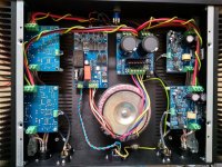
This is the first amp out of two 4-channels Mod-86 amps build. They will feed a 4-way system I'm designing. Currently it feeds a sort of 2-way speakers hand built by a sound engineer in Israel (Ariel Ran Liberman).
Initial impression is simply WOW! A couple of drivers on my current speakers were torn and I thought it impaired the whole system. With Tom's Mod-86 the speakers came back to life again. Every note and instrument stands for itself and there is no muffling at all. I never thought those speakers could sound so well.
The build was fairly easy. Tom's instructions are very well written and easy to follow. For any question Tom responds quickly via email. Couldn't ask for better support! Thanks Tom! This is my first project build (excluding O1 amp and blinking LED) and most of the struggle was with the case. I also made a some mistakes with the Mouser order that will be fixed in another time (ordered a toggle switch instead of momentary and a few others glitches).
Since it will be used for a stereo 4-way build, in the future I'll add a connection between the ISS boards to make them turn on (and maybe off too) together.
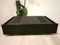
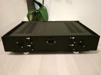
The case is Dissipante 2U from Modushop. Attached are some photos for you peepers who prefer to look at amps than listen to them
Initial impression is simply WOW! A couple of drivers on my current speakers were torn and I thought it impaired the whole system. With Tom's Mod-86 the speakers came back to life again. Every note and instrument stands for itself and there is no muffling at all. I never thought those speakers could sound so well.
The build was fairly easy. Tom's instructions are very well written and easy to follow. For any question Tom responds quickly via email. Couldn't ask for better support! Thanks Tom! This is my first project build (excluding O1 amp and blinking LED) and most of the struggle was with the case. I also made a some mistakes with the Mouser order that will be fixed in another time (ordered a toggle switch instead of momentary and a few others glitches).
Since it will be used for a stereo 4-way build, in the future I'll add a connection between the ISS boards to make them turn on (and maybe off too) together.
The case is Dissipante 2U from Modushop. Attached are some photos for you peepers who prefer to look at amps than listen to them
Attachments
Nice build! Thanks for sharing.
That depends entirely on the impedance and efficiency of the woofer.
On the other hand, in a multi-way system, each amp handles a slice of the total frequency range, thus, only a slice of the total output power. That eases the demands on the power supply a bit. That said, I'm just as happy to sell a Power-686 instead of the Power-86.
Tom
If you are planning to use this with a 4 way speaker then you should consider a different amp for the woofer.
That depends entirely on the impedance and efficiency of the woofer.
Your power supply is feeding 4 amps, Tom has a different ps with 4 caps , I would use one of those .
On the other hand, in a multi-way system, each amp handles a slice of the total frequency range, thus, only a slice of the total output power. That eases the demands on the power supply a bit. That said, I'm just as happy to sell a Power-686 instead of the Power-86.
Tom
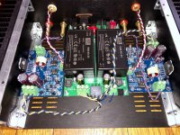
Here is my Modulus build. I am using a Mini-Dissipante chassis. The boards and instructions were great and it fired up and sounded great the first time! Kudos to Tom for the hard work!
I searched this thread about single-ended wiring and left the shield on the Modulus board floating. Every now and then I would get noise through the amp and moving the cables around resolved it. For kicks I put an alligator jumper from the shield pin on the Modulus board to the RCA shield and it then behaved! If you build this single-ended, HOOK UP THE SHIELD WIRE!
My other issue is that I built this for my Snell E-II's. These are my non-critical listening rock speakers. Sometimes I really like to crank it up and make the walls vibrate and I found the SMPS is NOT suited for that level of volume! It would start cycling on me as it hit the current limit.
Next step is to order the linear PS PCB from Tom and build this with a convential power supply. Live and learn! If anyone is interested in a fully-built and functional SMSP-86, drop me a line!
Attachments
Last edited:
If you build this single-ended, HOOK UP THE SHIELD WIRE!
I cover that on Page 11 of the design doc.
My other issue is that I built this for my Snell E-II's. These are my non-critical listening rock speakers. Sometimes I really like to crank it up and make the walls vibrate and I found the SMPS is NOT suited for that level of volume!
Yeah... The SMPS-86 is a good candidate for a desktop amp or an amp powering efficient 8 Ω speakers. If you're looking to rock your house off the foundation, you'll find the Power-86 or Power-686 to work better for you.
Tom
- Home
- Amplifiers
- Chip Amps
- Modulus-86 build thread