Tried google abbreviation and if it means self-resonant frequency i have to read up on that subject to have any serious meaning or thoght about it : ) then again is it stupid think some reason can be we do parelell capacitors to up its value but inductors need coupled in series to up value.
SRF = self-resonant frequency indeed.
The equivalent circuit for a capacitor is an inductor (ESL) in series with a resistor (ESR) in series with a capacitor (C). You'd expect a resonant frequency of SRF = 1/(2pi*sqrt(LC)). sqrt() = square root. Thus, if C increases, you would expect the SRF to decrease, thus, the lowest point in the curve (where you read the ESR) to shift down in frequency as C is increased.
In your measurement the resonant frequencies of the 1C -> 8C capacitors are smack on top of each other (approx. 1 kHz). That strikes me as odd. Does L decrease by N as you start adding more caps in parallel. In theory it does, but you're adding a lot of lead inductance with the clip leads, so the SRF should move. Your measurement doesn't show this movement, which makes me wonder why.
I don't think it's a limit of the test equipment. Rather, I think it's a limit of the test setup. I'd debug that and retake the data.
Test can be seen below with usual impedance curves plus advanced data for capacitor dialog, even shorted wire was tested as a capasitor and also tried inductance menu but it told component probably not was a inductor or vaule is below unit specs 0,05-100mH.
A piece of wire is an inductor. Figure roughly 1 nH/mm.
Neat instrument, though. It looks to be very useful for the hobbyist. For capacitor/inductor measurements you'll want the ability to calibrate out the lead inductance of the instrument itself. Does the software offer this option?
Tom
Last edited:
Hi BYRTT,
Your sampling frequency might be 44.1 KHz, but that means your bandwidth is going to be 1/2 of that. There has to be an anti-aliasing filter in there to prevent frequencies higher than 22.05 KHz from appearing as a false image, and since filters are no "brick wall" responses, you will lose some bandwidth to that. Notice how early CD players responded to information up to about 20 KHz? Same reason.
I'm not using an RTX6001 which samples at 192 KHz, and that allows me close to 96 KHz bandwidth at 24 bits or better. I'd have to look that figure up.
Beware of using too high a supply capacitance. Your conduction angle on the rectifier diodes becomes very small, which forces the peak currents to be much higher than they should be. This excited HF ringing, and you've read about that. Let's just say that it is easier to block a 120 Hz ripple than it is higher frequencies. So very high levels of capacitance actually harms you more than helps you.
Best, Chris
So very high levels of capacitance actually harms you more than helps you.
Very true. Too low ESR can be harmful as well. If the resonant Q of the decoupling and supply capacitance gets too high, you'll start having ringing on the power supply. That's not good either.
Some use snubbers to tame the Q. A well-placed electrolytic can will do the same thing.
Tom
Succesful build of an AMP
Hello Tom,
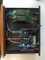
I just wanted to send you a picture about a succesful build of a stereo Modulus-86 based amplifier. Thanks for the support during the build! Sounds absolutely good, I'm very satisfied with sound quality!
I reused my old AMP's case and Heatsink for the build. Loudness was also tested (turned up the volume to approx same level, where my old AMP was), although the SMPS-86 turned to be just a little weak, when listening to "tchaikovsky 1812 overture"... When the cannons kicked in, the SMPS-86 went into overcurrent limit hickup mode, and restarted the amplifier
View attachment 705178
Nice! What is the stepped attenuator that you have in your build?
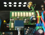
It's not a stepped attenuator, but a fully balanced preamp, based on Bruno Putzleys published preamp design, with alps potmeter, extended with an input selector(4 channels) , and implemented fully SMD, in order to be small enough to fit into the limited space I had. Psu is integrated LDO with 7A4700 and 7A3301, primarily running from the same +/- 24V, as the Modulus86.Nice! What is the stepped attenuator that you have in your build?
Hello Tom,
I just wanted to send you a picture about a succesful build of a stereo Modulus-86 based amplifier. Thanks for the support during the build! Sounds absolutely good, I'm very satisfied with sound quality!
Excellent. That's good to hear. It looks like a very nice build. I'd probably add some ventilation holes in the top and bottom above/below the heat sinks to allow them to breathe a bit better. That aside, it looks very nice.
I'm curious to see the front of the amp too. Show off that wood! Cherry?
SMPS-86 turned to be just a little weak, when listening to "tchaikovsky 1812 overture"... When the cannons kicked in, the SMPS-86 went into overcurrent limit hickup mode, and restarted the amplifier
Yeah. The 2.5 A output current of the SMPS-86 is not quite enough for a stereo amp - especially with 4 Ω load. That's why I generally recommend going for a dual-mono build if you're the type who likes to crank the music loud.
That said, as you also pointed out, exceeding the current limit is rather undramatic. Just annoying.
The SMPS-86 is great for a small desktop amp, though. For the money, and in terms of ease of use and compactness, it's hard to beat. Those wanting more power can ponder over the Mean Well RPS-200-27-C. A pair of those would drive the MOD86 to clipping with a 4 Ω load without much fuss.
Tom
Excellent. That's good to hear. It looks like a very nice build. I'd probably add some ventilation holes in the top and bottom above/below the heat sinks to allow them to breathe a bit better. That aside, it looks very nice.
I'm curious to see the front of the amp too. Show off that wood! Cherry?
Tom
The ventilation holes exists, just it was not visible on my previous picture.
I've got no pictures on my phone on the full-assembly, but it looks like an original amplifier. See the following link: Google Image Result for https://www.illel.fr/temp/an_photos/29438.jpg
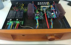
The front view of the Amplifier (including the MOD86):
(have to say: the woodwork is original from my old Amplifier, not my own work)

meszarosa - for those of us who might be interested in implementing an "integrated" amp with any of Tom's Modulus amps, could you share a URL for what appears to be a quite nicely implemented kit version of the Putzley design.
It's my own implementation. I live in Europe, and used "Eurocircuits" (PCB manufacturer) to produce this PCB. I can attach the Layout in PDF, which contains a reference number for the PCB. I assume, that number could be used to order a new set of PCB, if you're interested. View attachment PI_E1024933.pdf
There were two minor problems with the PCB, which could be easily fixed with manual patches. (Both based on schematic errors). However, in case of interest, I can fix them in the next release of the PCB, and make it public domain for builders. Send me Personal Message in case of interest.

The ventilation holes exists, just it was not visible on my previous picture.
Excellent. Carry on then.
The front view of the Amplifier (including the MOD86):
(have to say: the woodwork is original from my old Amplifier, not my own work)
Pretty, though.
Hey... What are those blue terminals on the MOD86 power connections? Are they just boots or do they terminate in a solid pin? I've been looking (although admittedly not very hard) for something that can turn a stranded wire into a solid pin for testing purposes.
Tom
Hello Tom, finnaly i have modulus 86 runing with my diy cirrus dac. I need some help regarding the connections. Do i need to put resistors or caps on the differential lines?
No need for any additional components on the differential lines. Just build the Modulus-86 according to the BOM and plug its input into the differential output of your DAC.
How is does thai1200 work?
Mostly by routing magic smoke between devices. It's that smoke that you let out when the part fries. Gotta keep it inside the part. This is important!
On a serious note: There's good description of how the THAT1200 works in its data sheet: THAT Corporation 1200-series InGenius High-CMRR Balanced Line Receiver ICs
Tom
- Home
- Amplifiers
- Chip Amps
- Modulus-86 build thread