Low gain Mod 76
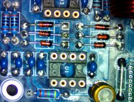
Built two low gain versions of this design to replace a failing Crown D-75 amp driving large format compression drivers @ 110db sensitivity. I used the That_1206, LM3876, MeanWell 24V power supplies and recycled the aluminum Crown chassis. Circuit boards are high quality and were a pleasure to assemble. The amp is dead silent with very lively dynamic response . Have ordered 4 more boards to fill out my tri-amped main speakers.
Built two low gain versions of this design to replace a failing Crown D-75 amp driving large format compression drivers @ 110db sensitivity. I used the That_1206, LM3876, MeanWell 24V power supplies and recycled the aluminum Crown chassis. Circuit boards are high quality and were a pleasure to assemble. The amp is dead silent with very lively dynamic response
. Have ordered 4 more boards to fill out my tri-amped main speakers.Attachments
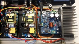
Nice build. I like the Mean Well RPS-200 supplies! They really make for a solid and compact build.
It looks like you used a plain nylon washer to secure the LM3886 to the heat sink. It might be a shoulder washer - I can't tell from the picture. You do want to make sure to use a proper shoulder washer (I give the P/N in Appendix A-1 of the design doc) to avoid having the screw contacting the LM3886. If you don't already, also make sure to isolate the LM3886 from the heat sink with a thermal pad such as the Wakefield K-10 or Keratherm.
I like the idea of reusing an existing chassis. That's some nice up-cycling there. Thanks for sharing.
I'll get your board order shipped when I return from the Vancouver Island DIY Fest. Expect them to ship Tuesday or Wednesday of the coming week. You'll see the "Order Complete" email once your boards ship.
Tom
It looks like you used a plain nylon washer to secure the LM3886 to the heat sink. It might be a shoulder washer - I can't tell from the picture. You do want to make sure to use a proper shoulder washer (I give the P/N in Appendix A-1 of the design doc) to avoid having the screw contacting the LM3886. If you don't already, also make sure to isolate the LM3886 from the heat sink with a thermal pad such as the Wakefield K-10 or Keratherm.
I like the idea of reusing an existing chassis. That's some nice up-cycling there.
Thanks for sharing.I'll get your board order shipped when I return from the Vancouver Island DIY Fest. Expect them to ship Tuesday or Wednesday of the coming week. You'll see the "Order Complete" email once your boards ship.
Tom
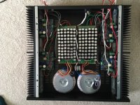
After two years of having these lying round without cases and posing an electrocution risk to all and sundry I finally boxed up my 4x Mod86p boards to make two bridged units.
Doesn't sound any different in a case but it sure looks better.
I wonder what project I can waste the next few years on?
Doesn't sound any different in a case but it sure looks better.
An externally hosted image should be here but it was not working when we last tested it.
I wonder what project I can waste the next few years on?
Nice,great job with the enclosures. I do believe those are parallel86 boards, lm4780 is the power chip.After two years of having these lying round without cases and posing an electrocution risk to all and sundry I finally boxed up my 4x Mod86p boards to make two bridged units.
You thinking about a new project? I know how you feel...
Last edited:
Nice to see the Parallel-86 in action. Thanks for sharing.
It looks like the Parallel-86 boards are just dangling by the LM4780. If that's indeed the case, I strongly suggest that you add standoffs at the four mounting holes in the PCB. Otherwise the LM4780 will either experience metal fatigue on its pins, which will cause all sorts of reliability issues, or the PCB will sag until it contacts the chassis.
Nice and tidy build otherwise. I like the chassis as well.
Tom
The standoffs have white nylon nuts attaching them to the pcb, you can't really discern them from the surrounding pad area, it's just a trick of the light, they're fully supported.
Ian, I like my cases to be big, the wiring is all displaced in vertical space to keep PSU, signal and Speaker wires a minimum of 5cm away from anything else at all times, that doesn't show up in the top down photo.
That said, those cases are big 250mm high 320mm long with an 8mm heatsink substrate. They ain't getting warm any time soon.
The standoffs have white nylon nuts attaching them to the pcb, you can't really discern them from the surrounding pad area, it's just a trick of the light, they're fully supported.
Excellent. All is well then.
That said, those cases are big 250mm high 320mm long with an 8mm heatsink substrate. They ain't getting warm any time soon.
You could probably fit another couple of Modulus channels on those heat sinks before you run out of heat sinking. That's a good problem to have. Cool is good.
Tom
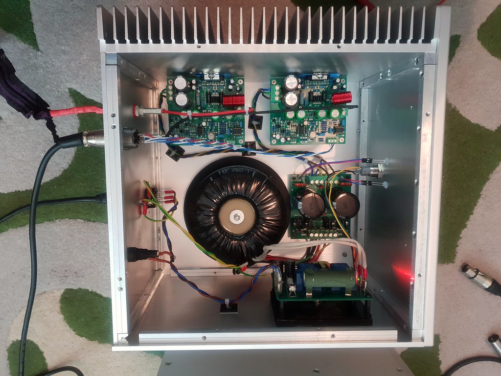
I've just finished building a 4 x Mod-86 amplifier to replace/improve-on my Densen DM10.
I decided to implement 4 modules to bi-amp my speakers with the longer term intention of taking the speakers active with a Minidsp.
Having built the amplifier (with some rather OTT power supplies), I've found that my speakers really don't like being bi-amped. I have no idea why, but going to to standard bi-wired onto two modules sounds much better.
The sound is astonishing. I've owned many power amps in my HiFi career and these are by far the best. The level of clarity is superb. I really don't have words to describe the beauty of reproduction of well recorded music with this. I thank you Tom, the value for money here is exceptional. I now have a second pair of modules to build an amp for my second system!
Attachments
The sound is astonishing. I've owned many power amps in my HiFi career and these are by far the best. The level of clarity is superb. I really don't have words to describe the beauty of reproduction of well recorded music with this. I thank you Tom, the value for money here is exceptional. I now have a second pair of modules to build an amp for my second system!
Wow. Thank you for your endorsement. I appreciate it.
Well... At least you got a bulk discount on the caps...
Nice build there! I'd consider cleaning up the supply wiring (from the supply to the MOD86es). Just bundle the wires tightly with cable ties. That'll reduce any supply-induced distortion. Nice build otherwise. Thanks for sharing.Tom
Brian, it’s 63 x 1000uf, 50V Panasonic caps. No idea why 63, the pcbs were bought via EBay. I worked on the principle that lots of smaller caps in parallel would be a lower impedance than a couple of larger ones. Without an A B comparison though I don’t know if there’s any real performance difference. The sound is certainly dynamic with instantaneous and powerful transients with deep sustained bass. Treble equally superb.
I worked on the principle that lots of smaller caps in parallel would be a lower impedance than a couple of larger ones.
In theory, putting multiple caps in parallel should result in a lower overall ESR. As usual, reality bites. You have two things working against you:
1) The ESR of a small cap is generally higher that that of a large cap.
2) The trace resistance of the PCB often ends up being larger that the raw ESR of a large cap.
So in reality, I doubt you'll see much (if any) ESR benefit of putting many small caps in parallel.
That said, I doubt the difference should be a cause for concern. If anything, the many small caps look much more impressive in the pictures and make for much better marketing than a few large caps.
The Modulus-86 is not sensitive to the power supply, so I suspect you won't hear any difference between a supply with large caps (my Power-86 and Power-686, for example) and a supply with many small caps in parallel. At least not in a blind test. We do hear with our eyes too (or rather what we see affects our perceptions in the audio domain).
Tom
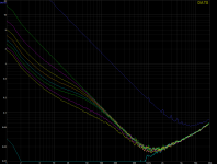
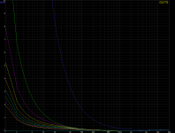
Should any be interested in measurements from cheaper diy affordable homegear as a Dayton DATS tool here is from one to eight times paralelled bigger Japanese capacitors, bigger is in they each have a huge 12,5mF value and being lazy they simply coupled together with cheap crocodile testwires which will add some RLC parasitics here and there. Second graph differ only in its a linear scale should some prefer, the higest impedance dark blue trace is for Rich Truss in its 1mF (Panasonic FC) and thereby same value he used in numbers of 63 into that nice build, and for fun and dreams the lowest light blue trace is a huge 35F low 2,7 voltage Cooper Bussmann HV1635-2R7356-R supercap. To be clear about all traces in graphs the eight same value 12,5mF parallelled ones is the the eight traces that unite as frq goes up, starting with one 12,5mF in upper green trace then in purle below there is 2x 12,5mF etc up to 8x 12,5mF in lower yellow trace.
Could be wrong here but as i see it we have a slower and slower battery impedance as frq goes down from up about 1kHz point looking from amp side, but seen from transformer/diode bridge side situation is in reverse having easyer load to those batteries as frg goes down. Don't know if this gives theoretical or measureable slow bass or not but if it does and where impecance numbers get worst then it should help recording material is mastered with some rolloff, and modern FIR DSP steered systems should be able dial in any slow excess phase that could be measured in a system.
Could be wrong here but as i see it we have a slower and slower battery impedance as frq goes down from up about 1kHz point looking from amp side, but seen from transformer/diode bridge side situation is in reverse having easyer load to those batteries as frg goes down. Don't know if this gives theoretical or measureable slow bass or not but if it does and where impecance numbers get worst then it should help recording material is mastered with some rolloff, and modern FIR DSP steered systems should be able dial in any slow excess phase that could be measured in a system.
Attachments
Last edited:
Data! Yes!
Note that the ESR doesn't change for eight caps in parallel. It remains 0.02 Ω (read at ~1 kHz).
I'm curious why the SRF doesn't change as you add caps.
The decrease in impedance seen in the 1-10 Hz region as you add caps is to be expected. 1*C has a higher impedance at 1 Hz than 8*C does. |1/(2pi*f*C)| and that...
Tom
...I'm curious why the SRF doesn't change as you add caps...
Tried google abbreviation and if it means self-resonant frequency i have to read up on that subject to have any serious meaning or thoght about it : ) then again is it stupid think some reason can be we do parelell capacitors to up its value but inductors need coupled in series to up value.
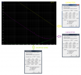
Maybe also we have bandwidth limitations in that DATS unit was in first place developed as a handy tool for diy speaker hobby and later on it got updated in software with real dialogs and menus for resistors/inductors/capacitors. Hardware interface to computer is seen from OS as a 16bit 32/44,1/48kHz USB soundcard, but its software say in manual is only accurate when interface is set locked at 44,1kHz and although scale on graphs can be adjusted to situation it can't show higher numbers than 20kHz. Those previous graphs was an old saved session that technically i can't do much about now, but for fun and insight did a new session using one Panasonic ECW-FD series PP 4,7uF plus a 22mF lytic from FC series and third test was shorted leads that show accurate same curve as that previous impressive 35F supercap and a raising impedance from 1kHz and up, and for info unit is as standard calibrated via a 0,1% 1k ohms resistor. Test can be seen below with usual impedance curves plus advanced data for capacitor dialog, even shorted wire was tested as a capasitor and also tried inductance menu but it told component probably not was a inductor or vaule is below unit specs 0,05-100mH.
Attachments
- Home
- Amplifiers
- Chip Amps
- Modulus-86 build thread