screen/shiled needs to be circular. If it's not circular then the core wire MUST be right in the geometric centre for the screen to work. Twisted pair or close coupled parallel pair are never in the geometirc centre.The right is too short...would need new wires. The left side might allow two turns. I'd much rather use shielding I have. I love using stuff lying around instead of tossing it.
Star quad can just about acheive that.
Brian, I just want to mention that there are at least two drawings, in the ON-SEMI pdf, that show the package curled or raised slightly off the heatsink surface. The example is the single screw mount, through the hole in the tab, LM3886 type. That is exactly why I was concerned before ever seeing the drawings. The design just struck me as something that could allow the main body to raise up, especially, after heating and cooling cycles. It is why I thought making a simple clamp, that would apply pressure on the main body, would be a good thing. I may still machine two for my stereo Mod86.
Hi Henry.
http://www.diyaudio.com/forums/chip-amps/265771-lm3886-thermal-experiment-data.html
LM3886 chip power amplifier thermal design.

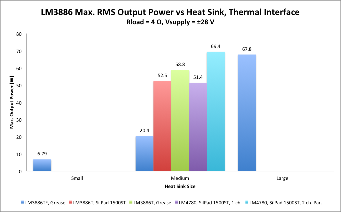
So, the insulated package with compound on large heatsink works perfectly well.
Lot's of ideas....
heatsink+spring
heatsink+spring+clip
heatsink+spring+mount
heatsink+spring+fastener


The above two spring clip types work very/perfectly well, BUT they are made of steel....IMHO/IME steel is not advisable directly over the actual amp chip.
If that titanium scrap is springy enough, I would try making a suitable copy of the lower pic.
These screw fixed spring clips allow easy removal/refit of the pcb/3886 to the heatsink.
To complete the OCD experimenting, you could try a range of HS compounds...the list of types is long, including Silver filled pastes, and Diamond filled pastes.
I reckon it's worth a try, and I expect some subtle subjective changes according to paste filler materials.
innovationcooling.com/how_it_works
Amazon - Diamond+thermal
Henry, have some fun with this project...once you have it running and you are familiar with the subjective sound quality, you can then have more fun experimenting with tweaks like the above and others like power filtering/snubbing and wire types....etc.
Dan.
http://www.diyaudio.com/forums/chip-amps/265771-lm3886-thermal-experiment-data.html
LM3886 chip power amplifier thermal design.
So, the insulated package with compound on large heatsink works perfectly well.
Thanks for the quote. I was the one conducting that experiment. The heat sink sizes were:
- "Small" = 13x13 cm aluminum sheet, 1.6 mm thick.
- "Medium" = Pentium Pro heat sink (Compaq P/N: 219222-006 NNE)
- "Large" = Heat sink specified at 0.4 ºK/W (about 2 kg of aluminum!)
The above two spring clip types work very/perfectly well, BUT they are made of steel....IMHO/IME steel is not advisable directly over the actual amp chip.
Unless you're messing with RF ICs with built-in VCOs, I wouldn't worry about steel touching the top of the package. I do agree that the spring clips are pretty awesome. I see them used everywhere.
Tom
10mm is over 3/8". Are we talking about the same thing?
Yes. Physics hurt at times.
I agree.
Twist EVERY Flow and Return Pair. Mains, Speaker, Signal, Power.
That's fine, but then you really need to run two ground (or power return, if you prefer) conductors. Twist one with the VCC and the other with VEE.
I don't agree with Tomchr on this ( and I don't have any numbers to prove my contention) one (1) twist per 2" (50mm) is better than no twists. You don't need 4 twists per inch to get good averaging of the fields for good attenuation of emi.
Assuming you get a good twist, that may be true. However, if you're using wire much fatter than 16 AWG (1 mm^2), you usually end up with a larger loop area and worse coupling due to the stiffness of the wire.
Cat5 uses tight twisting because the pairs are in contact with each other AND it is designed for >100MHz signaling.
So does microphone cable. Neither carry the kinds of load currents that we're talking about for the supply of a power amp. I fail to see how a 24 AWG twisted pair used for high-speed signalling with hardly any current flowing is directly comparable to a twisted power connection. The tradeoffs are vastly different.
The bottom line is that the wires should be tightly coupled. As I've mentioned many times, the Modulus-86 is not sensitive to EMI or power supply perturbations, so I wouldn't worry too much about twisting the supply connections. Also, as I mentioned yesterday, the worst offender is the connection from the transformer to the main supply caps. Focus on that. The rest is icing on the cake.
Tom
Assuming you get a good twist, that may be true. However, if you're using wire much fatter than 16 AWG (1 mm^2), you usually end up with a larger loop area and worse coupling due to the stiffness of the wire.
The bottom line is that the wires should be tightly coupled. the Modulus-86 is not sensitive to EMI or power supply perturbations, so I wouldn't worry too much about twisting the supply connections. .
Tom
Pic shows my wiring of transformer to pwr86 and prw86 to mod86s. All are 14awg and wires from pwr to mods are very short so won't lend themselves to twisting. Transformer wires are much longer but I get the impression that having the wires in intimate contact should be sufficient. that true? If so, I have lots of small tie wraps to hold wires together. I could even tie wrap all four transformers wires together if that is a better approach. Please let me know if I should bundle or reroute transformer to pwr86 wires away from the transformer?

Last edited:
Pic shows my wiring of transformer to pwr86 and prw86 to mod86s. All are 14awg and wires from pwr to mods are very short so won't lend themselves to twisting. Transformer wires are much longer but I get the impression that having the wires in intimate contact should be sufficient.
Looks very nice to me. I'd try to shorten the transformer wiring a bit. Mostly out of concern that one pair will get pinched between the top of the transformer mounting bolt (nice blue pad!) and the top plate of the chassis. On the longer run to the MOD86, I'd add a couple of wire ties.
Tom
Dan I really appreciate the info and links. About $0.30 and $5 shipping and I'm done.
On a side note about my wiring plan:
XLRs will be connected with 6" lengths of Belden 1192A Star Quad.
Wire to each Cardas post will be one 1" and one 1 1/2" long piece of 14awg PTFE coated OFHC copper. There's no way to twist those and they are so short I question the need to even tie wrap them together. All thoughts appreciated?
Last edited:
Wire to each Cardas post will be one 1" and one 1 1/2" long piece of 14awg PTFE coated OFHC copper. There's no way to twist those and they are so short I question the need to even tie wrap them together. All thoughts appreciated?
What do you think matters most? The 10-foot speaker cable connected on the outside of the binding post or the one inch connected on the inside?
From my view, it sounds like you have optimized the location of the binding posts. Hook 'em up and enjoy the music. The output of the amp is very low impedance, thus, nearly impossible to get to move with EMI.
Starquad! Nice!
Tom
I've spent many, many hours ready posts about soldering stations. They have options I never heard about and don't understand. I don't mind spending $250 for a device that appears to get rave reviews and has a good life span. Gotta check warranty...hope its at least one year.
I'm thinking a basic Metcal PS-900 would be plenty for me. From what i read it should easily heat up 12awg copper wire and binding posts, with the appropriate tip. The ones I saw online had labels reading made in china. Am i missing anything important? Are the ones from China clones?
I'm thinking a basic Metcal PS-900 would be plenty for me. From what i read it should easily heat up 12awg copper wire and binding posts, with the appropriate tip. The ones I saw online had labels reading made in china. Am i missing anything important? Are the ones from China clones?
Thanks Tom. Since you didn't mention it, I gather you think tie wrapping the other wires will do the job...no rerouting or anything else. Is that correct?
Correct. Add a zip tie or two. That's it.
Tom
Wiring
I didn't want to shorten the transformer wires in case I use it for something else or sell it. The top cover is 1 3/4" above the top of the blue bolt cap. I will add many wire ties. I bought way to many a few years ago. I am going to add two of those $.020 TO-220 spring steel clamps. I'll just feel better.Looks very nice to me. I'd try to shorten the transformer wiring a bit. Mostly out of concern that one pair will get pinched between the top of the transformer mounting bolt (nice blue pad!) and the top plate of the chassis. On the longer run to the MOD86, I'd add a couple of wire ties.
Tom
I am going to add two of those $.020 TO-220 spring steel clamps. I'll just feel better.
Awesome. That's a good way to go.
Tom, do you think 16 awg PTFE coated ofhc will be sufficient for 1 1/2" long wires from mod86 to binding posts? To your point, it's not ten feet of speaker cable. It will make things a little easier.
16 AWG is plenty for the 1.5" run, though if you have some speaker cable (zip cord) lying around, you may find that you can squeeze in even a 12 AWG wire. Speaker cable tends to have many more strands than hook-up wire, hence, be more flexible and easier to work with. The resistance from the amplifier output to the outside speaker cable is likely to be dominated by the contact resistance in the binding posts, so I wouldn't obsess too much over it, though. Many speakers - even higher end floor standers - are wired with wire thinner than 16 AWG and they're using a lot more than a few inches to do the job.
Your Teflon cables are likely coated with silver to prevent the Teflon from eating the copper (or adhere to the copper, I forget which). So the wire choice becomes whether you want the silver bling or the phat wire points...
") In the end, the difference in resistance between 1.5" of AWG16 and 1.5" of AWG12 is negligible.
In the end, the difference in resistance between 1.5" of AWG16 and 1.5" of AWG12 is negligible.Tom
Last edited:
I followed the advice from earlier in this thread on positioning and soldering the LM3886s and it worked really well. Now I just need to drill the holes for the PCB legs in the base plate in the right places and I'll be sorted.
Tom, next time you revise the manual I would suggest you include that guidance just in case someone doesn't take the time to read this thread.
And a question for you. Am I ok to perform the final checks without the LM 3886 fixed to the heatsink as long as I have a closely positioned fan blowing across it?
Tom, next time you revise the manual I would suggest you include that guidance just in case someone doesn't take the time to read this thread.
Maybe I'm being a bit too literal here, but which guidance is it that you suggest I include? Guidance on how to mount the LM3886 or guidance on how to drill the holes for the PCB?
And a question for you. Am I ok to perform the final checks without the LM 3886 fixed to the heatsink as long as I have a closely positioned fan blowing across it?
As long as you're only measuring the ±15 V and checking the output DC offset, you can do that without a heatsink or a fan. Don't try to drive any load, however.
I actually checked three Parallel-86 modules by clamping the LM4780 to a CPU heat sink using a small C clamp. It worked remarkably well. It's obviously not a production solution, but you can get away with quite a bit in prototyping.
Tom
- Home
- Amplifiers
- Chip Amps
- Modulus-86 build thread