Hi,
Today :
Tocos Cosmos RV24 10K with 10db pre-attenuation..
Just perfect, mid much "clean" and smooth, realy very good with voices or piano.
This pot is used on Kaneda amp for many years, I just understand why !
Phil.
Today :
An externally hosted image should be here but it was not working when we last tested it.
Tocos Cosmos RV24 10K with 10db pre-attenuation..
Just perfect, mid much "clean" and smooth, realy very good with voices or piano.
This pot is used on Kaneda amp for many years, I just understand why !
Phil.
You can't by right.
You could send a message to the Moderators and ask them to substitute a new post with the correct wording and attachments.
I have been told the Moderators will not modify a post for anyone.
I have been told it must be a complete "substitution" to remove the "error" in the original.
That's why it is preferable to use the Forum's attach facility, rather than using remote servers that automatically download enormous files when not required and can disappear leaving gaps in the posted information.
Well, I think that the thing to do is make a new post with attachments.
Below, click "Go Advanced" button, and then. . .
Scroll down just a little and click "Manage Attachments"
It would be great to have a schematic of your volume control arrangement.
I'd like to see that again.
Below, click "Go Advanced" button, and then. . .
Scroll down just a little and click "Manage Attachments"
It would be great to have a schematic of your volume control arrangement.
I'd like to see that again.
Oups, it's my fault, one folder on my server was deleted..
Picts of preamp with Tocos and pre att :
Picts of preamp with Tocos and pre att :
An externally hosted image should be here but it was not working when we last tested it.
An externally hosted image should be here but it was not working when we last tested it.
Missing picts on old mess :
An externally hosted image should be here but it was not working when we last tested it.
An externally hosted image should be here but it was not working when we last tested it.
An externally hosted image should be here but it was not working when we last tested it.
An externally hosted image should be here but it was not working when we last tested it.
An externally hosted image should be here but it was not working when we last tested it.
An externally hosted image should be here but it was not working when we last tested it.
An externally hosted image should be here but it was not working when we last tested it.
An externally hosted image should be here but it was not working when we last tested it.
An externally hosted image should be here but it was not working when we last tested it.
An externally hosted image should be here but it was not working when we last tested it.
An externally hosted image should be here but it was not working when we last tested it.
An externally hosted image should be here but it was not working when we last tested it.
An externally hosted image should be here but it was not working when we last tested it.
An externally hosted image should be here but it was not working when we last tested it.
An externally hosted image should be here but it was not working when we last tested it.
An externally hosted image should be here but it was not working when we last tested it.
I did not have, a quick draw :
But, after I add preatt (-7 db) directly on connectors amp :
If my note is right : Rs 15K and Rp 22K, and using same preamp (but without resistors att).
Resistors are Takman carbon.
Phil.
An externally hosted image should be here but it was not working when we last tested it.
But, after I add preatt (-7 db) directly on connectors amp :
An externally hosted image should be here but it was not working when we last tested it.
If my note is right : Rs 15K and Rp 22K, and using same preamp (but without resistors att).
Resistors are Takman carbon.
Phil.
")
Some questions
Hi Phil,
If you don't mind I have two questions for you...
This afternoon I finished the upgrade on my Chimp.com boards. I mounted the items mentioned in your thread.
The sound is GREAT! wow I did not expected this much change.. But with this upgrade came a Huge Thump when switching the amp on and of...Did you experienced the same or do you know what this could be?
The second things that I had a groundloop when connecting my balanced DAC (with RCA's). So I installed the Groundloop Breaker mentioned in your thread..
When I connect this breaker back to the chassis my isolated RCA connector do make contact with the Chassis again...is this right?
I ask this because I have enormous problems reading (even simple) schematics (long story) this problem became a big problem when I saw that the layout on the bridge rectifier is different to the schematic...
So I made a quick drawing of the original circuit (top) and my own version Bottom.
I would be very grateful if you could look at it... forgive me this probably simple questions
Raymond
Attachments
Hi Mark,
Thanks for the schematic. Maybe I see this wrong but since the RCA outer ring is connected to the ground plane of the PCB and the PCB is connect thru the resistor to the chassis there is still a connection? (The bieb on my multimeter says the same...) So the isolation on the RCA is lost?
Again forgive me, somehow this is not landing in the right spot or something like that..
The RCA return and the chassis are connected via the resistor and diodes. The resistance is low enough for the DMM to still indicate a connection, but high enough to reduce the currents racing around the ground network.
Post a photo of your build if you want conformation.
Post a photo of your build if you want conformation.
Last edited:
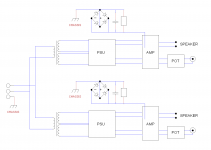
Well done Mark.Here is the schematic that I made for Philfr. It also shows the different ground connections to the chassis.
post94,
You show pairs of Flow and Return wires between each module.
I count 17 pairs in that drawing.
How I wish everyone would do the same.
Much of the "ground" loop problems just do not appear if everyone rigidly stuck to using PAIRs of Flow and Return wires for interconnections.
Last edited:
Hi,
At first I switch on amp, and after the dac.
It's due by bigger capacitors instead smaller at original schematic.
I draw all about safety loop breaker :
RCA sockets are isolated ?
Please post picts when you are ready.
Phil.
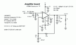
PS : see post one for complete schematic :
http://www.diyaudio.com/forums/chip-amps/265827-lm3886-fullrange.html#post4142277
Yes, I have, I must wait few seconds before switch off dac..But with this upgrade came a Huge Thump when switching the amp on and of...Did you experienced the same or do you know what this could be?
Raymond
At first I switch on amp, and after the dac.
It's due by bigger capacitors instead smaller at original schematic.
I draw all about safety loop breaker :
An externally hosted image should be here but it was not working when we last tested it.
RCA sockets are isolated ?
Please post picts when you are ready.
Phil.
PS : see post one for complete schematic :
http://www.diyaudio.com/forums/chip-amps/265827-lm3886-fullrange.html#post4142277
Last edited:
- Status
- This old topic is closed. If you want to reopen this topic, contact a moderator using the "Report Post" button.
- Home
- Amplifiers
- Chip Amps
- LM3886 "fullrange"