After reading the forum on the advantages of inverted Gainclones and looking at Joe's Valve-buffer. I decided to have a shot at this myself.
Joe's DIY version features a 6922 tube in cathode follower mode as a buffer.
The 6922 is basically the Soviet / Russian 6N23P tube. Looking at Klausmobile testfiles of the tube http://klausmobile.narod.ru/testerfiles/6n23p.htm made me sceptical of running the tube at 35V. It looks as if it is run in a highly unlinear fashion in Joe's circuit due to the low voltage.
Secondly, what bothered me was that Joe still saw the necessity to include a low-pass filter to get away the brightness/harshness of the buffered inverted gainclone. One might even conclude that the buffer didn't have the desired effect since the harshness problem seems to be related to the opamps feedback in IGC mode.
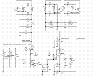
I decided to take this a bit further to bring the IGC idea to fruition with a simple but highly performant constant current buffer. "Micha" of the German tube forum Moehrenbude pointed out the LM334 three-pin chip to me which looks like an extremely simple solution as a constant current source. The slew rate specs of the chip are sufficient to accomodate the opamp.
Klausmobile recommended the 6N30P for low-voltage applications. Unfortunately this tube is hard to get and fairly expensive since it was mainly produced for Soviet military applications.
I went with another excellent tube with relatively low voltage capabilities, the 6N6P. http://klausmobile.narod.ru/testerfiles/6n6p.htm
I picked 10mA and 110V as my working point since this is within LM334 specs and at a fairly linear point on the 6N6P curves and gives me plenty of headroom. 10mA is right on the edge of the LM334 specs but that shouldn't be a problem because we running far below the max 0.4Watt. If this is not so then please someone could alert me.
The circuit shown can be easily adapted to use the 6922 / 6N23P tube. Simply look at Klausmobile 6N23P tracer files. I would probably try something like 6mA and 120V for the 6922. Don't take my word on it and please do your own experiments.
Since I like to keep things cheap I used two old 250Watt transformers which can deliver 127V AC for the tubes, 6.4V AC for the tube heaters and 18V AC for the LM3886. Transformer primaries are paralleled. One transformer deliveres the negative LM3886 voltage and tube anode voltage, the other transformer delivers positive LM3886 voltage and the tube heater voltage. I put some old 10000uF / 50V capacitors on the 28V rails.
The rest of the Gainclone circuit is fairly standard and can be adapted to one's minimalist of maximalist preference.
Overall, the current-injected valve-buffer is fairly simple to implement and should in theory eliminate all distortion from the valve-buffer since the tube is run at constant current.
This circuit is in theory the other extreme of what KYW suggested in his Hybrid Gain Klown Idea http://www.ampchipdiy.com/phpBB2/viewtopic.php?t=85
KYW circuit maximizes the (hopefully desired) distortion of the tube buffer while my circuit minimizes it.
Any suggestions for improvement are highly welcome.
Sound
How does it sound ? Just marvelous. Great bass, very clear sound without being harsh or bright, no ripple, hum etc.
I ran first on one channel the plain IGC and on the other channel the Current-injected tube-buffered IGC to hear the difference.
After listening to the buffered channel for some time it became almost unbearable to hear the plain IGC because the harshness / brightness was just too much.
I don't hear any need for a low-pass filter as in Joe's circuit.
Tubes
I ran the curcuit with two different types of the 6N6P tube, a plain 6N6P and a 6N6P-I. Both tubes were bought used and gave quite different Grid-cathode voltages with the same current setting. I couldn't hear any difference between them which suggests to me that the LM334 is extremely efficient in flatening the current.
In contrast to this my circuit tries to keep the original IGC idea in it's purest form and eliminate the non-constant feedback without adding tube distortion.
Any critique is highly welcome. Surely the gurus will like to add to my humble idea.
Gerry
Joe's DIY version features a 6922 tube in cathode follower mode as a buffer.
The 6922 is basically the Soviet / Russian 6N23P tube. Looking at Klausmobile testfiles of the tube http://klausmobile.narod.ru/testerfiles/6n23p.htm made me sceptical of running the tube at 35V. It looks as if it is run in a highly unlinear fashion in Joe's circuit due to the low voltage.
Secondly, what bothered me was that Joe still saw the necessity to include a low-pass filter to get away the brightness/harshness of the buffered inverted gainclone. One might even conclude that the buffer didn't have the desired effect since the harshness problem seems to be related to the opamps feedback in IGC mode.
I decided to take this a bit further to bring the IGC idea to fruition with a simple but highly performant constant current buffer. "Micha" of the German tube forum Moehrenbude pointed out the LM334 three-pin chip to me which looks like an extremely simple solution as a constant current source. The slew rate specs of the chip are sufficient to accomodate the opamp.
Klausmobile recommended the 6N30P for low-voltage applications. Unfortunately this tube is hard to get and fairly expensive since it was mainly produced for Soviet military applications.
I went with another excellent tube with relatively low voltage capabilities, the 6N6P. http://klausmobile.narod.ru/testerfiles/6n6p.htm
I picked 10mA and 110V as my working point since this is within LM334 specs and at a fairly linear point on the 6N6P curves and gives me plenty of headroom. 10mA is right on the edge of the LM334 specs but that shouldn't be a problem because we running far below the max 0.4Watt. If this is not so then please someone could alert me.
The circuit shown can be easily adapted to use the 6922 / 6N23P tube. Simply look at Klausmobile 6N23P tracer files. I would probably try something like 6mA and 120V for the 6922. Don't take my word on it and please do your own experiments.
Since I like to keep things cheap I used two old 250Watt transformers which can deliver 127V AC for the tubes, 6.4V AC for the tube heaters and 18V AC for the LM3886. Transformer primaries are paralleled. One transformer deliveres the negative LM3886 voltage and tube anode voltage, the other transformer delivers positive LM3886 voltage and the tube heater voltage. I put some old 10000uF / 50V capacitors on the 28V rails.
The rest of the Gainclone circuit is fairly standard and can be adapted to one's minimalist of maximalist preference.
Overall, the current-injected valve-buffer is fairly simple to implement and should in theory eliminate all distortion from the valve-buffer since the tube is run at constant current.
This circuit is in theory the other extreme of what KYW suggested in his Hybrid Gain Klown Idea http://www.ampchipdiy.com/phpBB2/viewtopic.php?t=85
KYW circuit maximizes the (hopefully desired) distortion of the tube buffer while my circuit minimizes it.
Any suggestions for improvement are highly welcome.
Sound
How does it sound ? Just marvelous. Great bass, very clear sound without being harsh or bright, no ripple, hum etc.
I ran first on one channel the plain IGC and on the other channel the Current-injected tube-buffered IGC to hear the difference.
After listening to the buffered channel for some time it became almost unbearable to hear the plain IGC because the harshness / brightness was just too much.
I don't hear any need for a low-pass filter as in Joe's circuit.
Tubes
I ran the curcuit with two different types of the 6N6P tube, a plain 6N6P and a 6N6P-I. Both tubes were bought used and gave quite different Grid-cathode voltages with the same current setting. I couldn't hear any difference between them which suggests to me that the LM334 is extremely efficient in flatening the current.
In contrast to this my circuit tries to keep the original IGC idea in it's purest form and eliminate the non-constant feedback without adding tube distortion.
Any critique is highly welcome. Surely the gurus will like to add to my humble idea.
Gerry
Attachments
Konnichiwa,
I would switch the LM334 for a J-Fet CCS or Cascode it with a suitable J-Fet and return the CCS to a highish voltage negative rail.
We have tried LM334 & J-Fet Cascoded LM334, J-Fet, Cascoded J-Fet and C4S as "tails in Long tailed pairs, the preference was for casoded J-Fets, then J-Fet with cascoded LM334 and C4S tied, LM334 was worst.
I would also cascode the Follower valve and if neccesary double the Anode Voltage, using a vaoltage doubler..
That is I PERSONALLY actually would shift to a Valve Stage for the voltage gain and the LM3875 as inverting Follower. You might want to try this too.
Sayonara
Gerry said:Any suggestions for improvement are highly welcome.
I would switch the LM334 for a J-Fet CCS or Cascode it with a suitable J-Fet and return the CCS to a highish voltage negative rail.
We have tried LM334 & J-Fet Cascoded LM334, J-Fet, Cascoded J-Fet and C4S as "tails in Long tailed pairs, the preference was for casoded J-Fets, then J-Fet with cascoded LM334 and C4S tied, LM334 was worst.
I would also cascode the Follower valve and if neccesary double the Anode Voltage, using a vaoltage doubler..
That is I PERSONALLY actually would shift to a Valve Stage for the voltage gain and the LM3875 as inverting Follower. You might want to try this too.
Sayonara
Interesting.
Hi Gerry,
It would be great to see the physical implementation also.
From the circuit configuration it would look like you say that the chip is not harsh at HF . The CCS would improve the performance of the tube , not the chip.
However it looks like in the earlier implementation with the tube , the chip had a filter at the input of the chip to tame a HF problem with the chip- at 300KHz or so .
Does this go away with your circuit ?
Have you had the opportunity to hear the earlier implementation ? If so I would like to know if they sound any different. I am in the process of building a GC and would like to do it best the first time. There wouldn't be time to redo it.
Thanks.
Cheers,
Ashok.
Konnichiwa,
Silly me and I thought it was merely a (unneccesary) lead/lag compensation cap....
Sayonara
Pedja said:Gerry, C8 is no-no. You can use it only as a part of a higher order filter.
Silly me and I thought it was merely a (unneccesary) lead/lag compensation cap....
Sayonara
various
Gregc,
an oversight - indeed there is one. Basically it's a very small resistor with a fat wire wound around it as an inductor.
Pedja,
C8 is recommended by National Semiconductor. "Reduces the gain (bandwidth of the amplifier) at high frequencies to avoid quasi-saturation oscillations of the output transistor. The capacitor also suppresses external electromagnetic switching noise created from fluorescent lamps to suppress HF oscillations from neon bulbs switchers." http://cache.national.com/ds/LM/LM3886.pdf
See page 8 point 6. It's optional.
I didn't hear any sound difference whatsoever when putting it in - so why not leave it there if they recommend it.
Ashok,
True, but additionally the harshness of the "naked" IGC goes away - I would guess due to improved feedback. A low-pass filter as in Joe's circuit doesn't seem to be necessary.
No. Basically it made no sense to me to run the tube starved of voltage. Let's remember that Joe Rasmussen has only published the watered-down version of the real McCoy - his commercial product. The commercial product does include a current source as my circuit - and if I would have to make a guess I suspect that he is running in the commercial product the valve at the higher (proper) voltages and not starved at 35V as suggested in his DIY circuit.
If one really wants to hear the tube distortion then simply replace the LM334 with a 300 Ohm resistor - or insert a switch to switch between either the LM334 or the resistor so you can have it both ways - but with the proper voltage on the tube.
I will publish a photo of the physical layout as soon as the thing is boxed. It's breadboard design now.
KYW,
Why ?
Why ? The LM334 sounds absolutely neutral - at least to my ears.
You want to maximize the tube distortion. That idea gives an entirely sound since my circuit minimizes the tube distortion.
Gerry
Gregc,
You may want to add a res in par. of L1.
an oversight - indeed there is one. Basically it's a very small resistor with a fat wire wound around it as an inductor.
Pedja,
C8 is recommended by National Semiconductor. "Reduces the gain (bandwidth of the amplifier) at high frequencies to avoid quasi-saturation oscillations of the output transistor. The capacitor also suppresses external electromagnetic switching noise created from fluorescent lamps to suppress HF oscillations from neon bulbs switchers." http://cache.national.com/ds/LM/LM3886.pdf
See page 8 point 6. It's optional.
I didn't hear any sound difference whatsoever when putting it in - so why not leave it there if they recommend it.
Ashok,
The CCS would improve the performance of the tube , not the chip.
True, but additionally the harshness of the "naked" IGC goes away - I would guess due to improved feedback. A low-pass filter as in Joe's circuit doesn't seem to be necessary.
Have you had the opportunity to hear the earlier implementation ?
No. Basically it made no sense to me to run the tube starved of voltage. Let's remember that Joe Rasmussen has only published the watered-down version of the real McCoy - his commercial product. The commercial product does include a current source as my circuit - and if I would have to make a guess I suspect that he is running in the commercial product the valve at the higher (proper) voltages and not starved at 35V as suggested in his DIY circuit.
If one really wants to hear the tube distortion then simply replace the LM334 with a 300 Ohm resistor - or insert a switch to switch between either the LM334 or the resistor so you can have it both ways - but with the proper voltage on the tube.
I will publish a photo of the physical layout as soon as the thing is boxed. It's breadboard design now.
KYW,
I would ... return the CCS to a highish voltage negative rail.
Why ?
I would also cascode the Follower valve and if neccesary double the Anode Voltage, using a vaoltage doubler..
Why ? The LM334 sounds absolutely neutral - at least to my ears.
That is I PERSONALLY actually would shift to a Valve Stage for the voltage gain and the LM3875 as inverting Follower.
You want to maximize the tube distortion. That idea gives an entirely sound since my circuit minimizes the tube distortion.
Gerry
Re: various
Konnichiwa,
More headroom for signal. I suspect your setup is a bit marginal. How much voltage swing do you have across the LM334 and how much static voltage
Compared to what?
I don't think so. The 5687 as shown is very linear. But it provides a certain degree of "tube magic" in my experience not present with a follower.
Then why not use a cascoded FET buffer from the positive rail of the LM3875 and a cascoded FET currentsource from the negative rail, or indeed use a BUF634?
BTW, in my experience, Cathode followers are usually MORE coloured than simple, well applied common cathode stages using the same valve, this is retained through current sourced and cascoded versions, though such minimise the audible impact.
But if you like the result, fine.
Sayonara
Konnichiwa,
Gerry said:Why ?
More headroom for signal. I suspect your setup is a bit marginal. How much voltage swing do you have across the LM334 and how much static voltage
Gerry said:The LM334 sounds absolutely neutral - at least to my ears.
Compared to what?
Gerry said:You want to maximize the tube distortion.
I don't think so. The 5687 as shown is very linear. But it provides a certain degree of "tube magic" in my experience not present with a follower.
Gerry said:That idea gives an entirely sound since my circuit minimizes the tube distortion.
Then why not use a cascoded FET buffer from the positive rail of the LM3875 and a cascoded FET currentsource from the negative rail, or indeed use a BUF634?
BTW, in my experience, Cathode followers are usually MORE coloured than simple, well applied common cathode stages using the same valve, this is retained through current sourced and cascoded versions, though such minimise the audible impact.
But if you like the result, fine.
Sayonara
Re: various
That cap alone alters the phase inside the loop (reduces the phase margin) and thus violates the stability. The 50pF-20k in parallel with 20k feedback resistor you see in National’s datasheet will correct this (though I think it will do only partially). You might try to go entirely passive i.e. outside the loop.
Huh, how many complainers here… Sorry… With a few corrections, you in fact made a nice amp.
Pedja
Gerry,Gerry said:C8 is recommended by National Semiconductor. "Reduces the gain (bandwidth of the amplifier) at high frequencies to avoid quasi-saturation oscillations of the output transistor. The capacitor also suppresses external electromagnetic switching noise created from fluorescent lamps to suppress HF oscillations from neon bulbs switchers." http://cache.national.com/ds/LM/LM3886.pdf
See page 8 point 6. It's optional.
I didn't hear any sound difference whatsoever when putting it in - so why not leave it there if they recommend it.
That cap alone alters the phase inside the loop (reduces the phase margin) and thus violates the stability. The 50pF-20k in parallel with 20k feedback resistor you see in National’s datasheet will correct this (though I think it will do only partially). You might try to go entirely passive i.e. outside the loop.
Huh, how many complainers here… Sorry… With a few corrections, you in fact made a nice amp.
Pedja
KYW
KYW,
Grid to cathode voltage is ample - approx. 3V depending on age of tube. Grid swing amplitude is typically up to 0.8V. The LM334 needs to "see" one Volt minimum voltage to function as specified - this leaves 2V effective headroom. I haven't managed to clip it. It's more likely that the neighbours will alert the police due to emerging cracks in ceiling before that happens.
There are of course various ways to construct a current source. My main concern apart from the sufficient sourcing capabilities was whether the LM334 slew rate is sufficient. National Semiconductor says so and my ears can't hear any different either.
Harmonic distortion is entirely a function of current swing. I would be surprised to see a zero current swing on the cathode giving more distortion than a zero current swing on the anode. I might be ignorant, but as far as I am concerned the slew rate of the LM334 virtually guarantees that the swing is indeed zero.
BTW: I am puzzled. The IGC in the DIY community has been mainly your baby. Due to your own experience and various discussions you must have been aware of the excessive harshness/brightness due to the feedback problem of the unbuffered IGC. It appears as if the brightness problem caused people to abandon the IGC in droves to head for the NIGC.
Unfortunately, I couldn't find any posting of you showing one of your tested preferred buffers which adress the problem. Surely, ANY of them must have been better than your originally proposed "naked" IGC ?!
As far as I can see the IGC is in principle superior to the NIGC if it is assisted by a proper buffer. You still seem to agree with this since you used an IGC in your latest tubey-sound opamp setup.
Anyway, if your favourite constant current buffer doesn't involve diamond-plated nuke-powered batteries I am keen to run it side by side with my circuit and let my wife blindly decide which sounds better. Which one is it ? Please post scheme.
Regarding your freshly proposed idea to use the tube for the voltage swing and harmonic fingerprint and the opamp purely for the power, I suggest to discuss it on the forum you posted it on. Unfortunately you have been a bit cagey regarding the details lurking behind it. http://www.ampchipdiy.com/phpBB2/vi...start=15&sid=8d90ebb73db973116a43bb3af3b5e7f2
Gerry
KYW,
<How much voltage swing do you have across the LM334 and how much static voltage>
Grid to cathode voltage is ample - approx. 3V depending on age of tube. Grid swing amplitude is typically up to 0.8V. The LM334 needs to "see" one Volt minimum voltage to function as specified - this leaves 2V effective headroom. I haven't managed to clip it. It's more likely that the neighbours will alert the police due to emerging cracks in ceiling before that happens.
Then why not use a ......
There are of course various ways to construct a current source. My main concern apart from the sufficient sourcing capabilities was whether the LM334 slew rate is sufficient. National Semiconductor says so and my ears can't hear any different either.
BTW, in my experience, Cathode followers are usually MORE coloured than simple, well applied common cathode stages using the same valve, this is retained through current sourced and cascoded versions, though such minimise the audible impact.
Harmonic distortion is entirely a function of current swing. I would be surprised to see a zero current swing on the cathode giving more distortion than a zero current swing on the anode. I might be ignorant, but as far as I am concerned the slew rate of the LM334 virtually guarantees that the swing is indeed zero.
BTW: I am puzzled. The IGC in the DIY community has been mainly your baby. Due to your own experience and various discussions you must have been aware of the excessive harshness/brightness due to the feedback problem of the unbuffered IGC. It appears as if the brightness problem caused people to abandon the IGC in droves to head for the NIGC.
Unfortunately, I couldn't find any posting of you showing one of your tested preferred buffers which adress the problem. Surely, ANY of them must have been better than your originally proposed "naked" IGC ?!
As far as I can see the IGC is in principle superior to the NIGC if it is assisted by a proper buffer. You still seem to agree with this since you used an IGC in your latest tubey-sound opamp setup.
Anyway, if your favourite constant current buffer doesn't involve diamond-plated nuke-powered batteries I am keen to run it side by side with my circuit and let my wife blindly decide which sounds better. Which one is it ? Please post scheme.
Regarding your freshly proposed idea to use the tube for the voltage swing and harmonic fingerprint and the opamp purely for the power, I suggest to discuss it on the forum you posted it on. Unfortunately you have been a bit cagey regarding the details lurking behind it. http://www.ampchipdiy.com/phpBB2/vi...start=15&sid=8d90ebb73db973116a43bb3af3b5e7f2
Gerry
Hybrid clone with feedback around opamp
Perhaps this design offered by John Brosky? The LM3875 or LM3886 *might* work in place of the LM12, but the LM12 is stable at gain levels which are considered to be at the bottom of the range recommended by National Semiconductor.
-Tom
Perhaps this design offered by John Brosky? The LM3875 or LM3886 *might* work in place of the LM12, but the LM12 is stable at gain levels which are considered to be at the bottom of the range recommended by National Semiconductor.
-Tom
Hybrid clone with feedback around opamp
If any is curious about the Tube Cad Journal article the circuit was mentioned in it was here: http://www.tubecad.com/index_files/page0023.htm
-Tom
If any is curious about the Tube Cad Journal article the circuit was mentioned in it was here: http://www.tubecad.com/index_files/page0023.htm
-Tom
Re: KYW
Konnichiwa,
The output swing of the Lm3875 on the usual 35V rails is around +/-30V. This requires an input swing of around 30/22=1.4V. Doing this with only 3V static Voltage across the LM334 may work but is hardly ideal, refering to FET CCS who also SHOULD saturate with only 1V.
Do you believe there is an inherent relation between harmonic distortion and good sound? Then you made the sound of your Amp better by adding a lot of HD, compared to the previous state.
I have heard several non-buffered IGC's that did not have the sound you describe.
I noticed many a fashion. One day the 300B is the best tube, the other the 2A3, then the 45, but no, the 10 is best, no only 845's at low voltage sound good, hey, chipamp's are THE thing, hey, inverted chipamp's are the thing, hey, noninverted chipamps are the thing and so on. In the very rarest of these cases are these opinions formed in "all else being equal" listening tests with a reasonable attemp being made to eliminate bias.
Once you talk different systems, implementations, passive parts etc you cannot any long draw valid comparisons.
If you like an IGC with valve buffer, with LPF or without, inverting or not, if it sounds good to you, have fun and more power to you.
I did not criticise your design, I merely pointed out a few things I feel may make an audible change. Just like I feel that virtually ANY Op-Amp sounds better inverted, all else being equal. You don't HAVE to try it, but you asked opinions. Those I gave where mine.
What problem? I do know of one IGC that shortly aquired a buffer and quickly lost it again. All in all system interactions and tastes vary.
Why?
Even without buffer. But as said, much of this is a moot point. I fully suspect someone to try the inverted circuit after a year or so of listening non-inverted, or bypass the buffer and finding the result superior and then many people will re-build their AMp's again. So what (shrug).
It doesn't. Simply use a TX-102 as Volume control. Compare to any other setup you like.
Hardly cagey. The circuit is straightforward.
Sayonara
Konnichiwa,
Gerry said:Grid to cathode voltage is ample - approx. 3V depending on age of tube. Grid swing amplitude is typically up to 0.8V.
The output swing of the Lm3875 on the usual 35V rails is around +/-30V. This requires an input swing of around 30/22=1.4V. Doing this with only 3V static Voltage across the LM334 may work but is hardly ideal, refering to FET CCS who also SHOULD saturate with only 1V.
Gerry said:Harmonic distortion is entirely a function of current swing. I would be surprised to see a zero current swing on the cathode giving more distortion than a zero current swing on the anode. I might be ignorant, but as far as I am concerned the slew rate of the LM334 virtually guarantees that the swing is indeed zero.
Do you believe there is an inherent relation between harmonic distortion and good sound? Then you made the sound of your Amp better by adding a lot of HD, compared to the previous state.
Gerry said:BTW: I am puzzled. The IGC in the DIY community has been mainly your baby. Due to your own experience and various discussions you must have been aware of the excessive harshness/brightness due to the feedback problem of the unbuffered IGC.
I have heard several non-buffered IGC's that did not have the sound you describe.
Gerry said:It appears as if the brightness problem caused people to abandon the IGC in droves to head for the NIGC.
I noticed many a fashion. One day the 300B is the best tube, the other the 2A3, then the 45, but no, the 10 is best, no only 845's at low voltage sound good, hey, chipamp's are THE thing, hey, inverted chipamp's are the thing, hey, noninverted chipamps are the thing and so on. In the very rarest of these cases are these opinions formed in "all else being equal" listening tests with a reasonable attemp being made to eliminate bias.
Once you talk different systems, implementations, passive parts etc you cannot any long draw valid comparisons.
If you like an IGC with valve buffer, with LPF or without, inverting or not, if it sounds good to you, have fun and more power to you.
I did not criticise your design, I merely pointed out a few things I feel may make an audible change. Just like I feel that virtually ANY Op-Amp sounds better inverted, all else being equal. You don't HAVE to try it, but you asked opinions. Those I gave where mine.
Gerry said:Unfortunately, I couldn't find any posting of you showing one of your tested preferred buffers which adress the problem.
What problem? I do know of one IGC that shortly aquired a buffer and quickly lost it again. All in all system interactions and tastes vary.
Gerry said:Surely, ANY of them must have been better than your originally proposed "naked" IGC ?!
Why?
Gerry said:As far as I can see the IGC is in principle superior to the NIGC if it is assisted by a proper buffer.
Even without buffer. But as said, much of this is a moot point. I fully suspect someone to try the inverted circuit after a year or so of listening non-inverted, or bypass the buffer and finding the result superior and then many people will re-build their AMp's again. So what (shrug).
Gerry said:Anyway, if your favourite constant current buffer doesn't involve diamond-plated nuke-powered batteries I am keen to run it side by side with my circuit and let my wife blindly decide which sounds better.
It doesn't. Simply use a TX-102 as Volume control. Compare to any other setup you like.
Gerry said:Regarding your freshly proposed idea to use the tube for the voltage swing and harmonic fingerprint and the opamp purely for the power, I suggest to discuss it on the forum you posted it on. Unfortunately you have been a bit cagey regarding the details lurking behind it.
Hardly cagey. The circuit is straightforward.
Sayonara
Re: Re: KYW
Although I converted all the amps to NI config., I still keep one inveritng amp in my basement workshop system, as it seems to me that it sounds so good in there, that changing it wouldn't bring any improvement. I had an NI amp for a short while in that system and was not impressed at all. But when I try the amps in different setups, my prefference is different too. So it is very system dependant. For the record, I never found IGC harsh or bright. After switching to the other amps it seems to me that IGC was actually rather veiled and less detailed, but again it's only my observation.
Kuei Yang Wang said:I fully suspect someone to try the inverted circuit after a year or so of listening non-inverted, or bypass the buffer and finding the result superior and then many people will re-build their AMp's again. So what (shrug).
Although I converted all the amps to NI config., I still keep one inveritng amp in my basement workshop system, as it seems to me that it sounds so good in there, that changing it wouldn't bring any improvement. I had an NI amp for a short while in that system and was not impressed at all. But when I try the amps in different setups, my prefference is different too. So it is very system dependant. For the record, I never found IGC harsh or bright. After switching to the other amps it seems to me that IGC was actually rather veiled and less detailed, but again it's only my observation.
Current-injected buffered gainclone, anyone improvements recently ?
Hi there,
I would love to hear whether there have been any further insights/improvements in the last years regarding valve-buffered gainclones with current source ? See my design at the start of this thread.
I see one design published which uses a JFET as a current source, see Option 3 by Maarten here:
Tubeclone 2
It appears to me that many of the gainclone afficionados dont try designs with tubes due to the extra challenges involved. Also the valve/tube guys do in tendency not get involved with opamps. Unfortunately this limits somewhat the further development of such hybrids. Which is a pity IMO because such designs can deliver really great sound for little money.
Cheers
Gerry
I've used tube input stages with some power amps including some chip amps.
The listening tests showed me that I cannot automatically assume that adding a tube front end is going to make the amp sound 'better' or 'nicer'. In some cases it was better sounding but in other systems it did strange things like 'sanitise' the sound. What was VERY dynamic in the bass end was converted to just ordinary sound. By ordinary sound I mean the sound we hear from many average systems which are 'nice sounding'. Component changes didn't improve things.
The only way you can determine how it will sound ' in your system' is to try it out. I'm almost convinced that no one else can give you an answer that would apply exactly for your system. But yes, it "could" make a big difference and unfortunately you will have to try it out yourself to find out !
If it doesn't , don't be disappointed . There will be other combinations which might get you what you want in your system. It would mean that you have just reached a major junction on your long DIY ride ! But there is a LONG way ahead with probably some more great junctions on the way!
- Status
- This old topic is closed. If you want to reopen this topic, contact a moderator using the "Report Post" button.
- Home
- Amplifiers
- Chip Amps
- Current-injected Valve-buffered Gainclone