I purchased this amplifier kit.
I have put it all together, but when I hook it up to speakers and power it up with 12.6 volts AC the amp heats up really quick and emits a loud humming noise out of the left speaker only. The humming noise is the same regardless of the volume setting. I am thinking that one of the TDA2030 transistors are bad, but I am not sure. There is a burning smell and after only a few seconds the rectifier diodes and the heatsinks on the amplifier chips become too hot to touch!
This occurs even if there is no input audio and the volume is all the way down!
As soon as I unhook the speakers however, the amp cools down and there is no burning smell. The same speakers work fine when hooked up to another amplifier (Lepai 838) and the speakers measure 4 ohms each. The speakers are 70 watts RMS.
I have also tested various components on the board with an ohmmeter and nothing appears to be shorted. Although one thing I noticed is that I read 17 volts on the outputs of the amp with the speakers unhooked with nothing on the input and I am not sure if this is normal (maybe I need capacitors on the outputs?).
You might be having DC at o/p. Chk PSU for proper +/- ve supply using series bulb (any cheapo from car) & also at supply pins of 2030-
1 Fake /Faulty 2030 chips.
2 Remember the heatsink is -ve, make sure nothing is touching to it.
3 No caps at o/p because this looks direct coupled bipolar implementation. You can use series R (say 100 Ohms) between your spk (pref. cheapish) for any further testing.
1 Fake /Faulty 2030 chips.
2 Remember the heatsink is -ve, make sure nothing is touching to it.
3 No caps at o/p because this looks direct coupled bipolar implementation. You can use series R (say 100 Ohms) between your spk (pref. cheapish) for any further testing.
Last edited:
These kits are cheap for a reason. If you're sure you didn't make a mistake in building, you probably have a bad IC. I've purchased ICs off eBay with shorted outputs. They don't even test them! Since the TDA2030A, 2040 and 2050 are now obsolete parts, it may be difficult getting authentic ones. Try an LM1875 from Mouser or Digikey. It is practically a direct plug in replacement.
Availlytics, look more carefully. This is a single supply implementation with capacitor coupled outputs and the heat sinks will be at ground potential.
Availlytics, look more carefully. This is a single supply implementation with capacitor coupled outputs and the heat sinks will be at ground potential.
.
Power supply overheats, and there's a 120 Hz hum. There's gotta be a fault in the power connections--though that might not be the only fault. Along that line:
I'm all in favor of buying kits, they're a good way to get your feet wet. That remaining so:
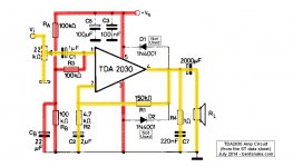
The circuit you're using (on the eBay page) has only minor changes from the ST data sheet schematic, which I post below for reference. There's a very good reason for this "only minor changes."
The reason is that chips are not designed in a vacuum. Rather, they're designed to work in a given circuit, which is the one given in the data sheet. Equipment manufacturers down the line might make small or large changes to the original data sheet circuit, but they're always working with that original bedrock circuit because that's how the chip was designed to work, and it doesn't work any other way.
I'm trying to sell you on the idea that the factory circuit works, it always works, it's guaranteed to work, and it's impossible for it not to work. Which leads to the inevitable conclusion.
Lookee, I hate to come in sounding like the all-wise, or Sammy Smartmouth or somobody, but there's just no getting around the fact that you soldered something up wrong. If it makes you feel any better, you're not exactly the first.
The way to fix this is not as bad as it sounds. Start at pin one of the chip and see what's connected. Compare this to what the schematic says should be connected. Then pin two, and on down the line.
Power supply connections, same thing. Ground connections, same thing. I know this sounds like it will take hours, but it really doesn't. It helps to write things down.
That's my say on the subject. But some additional notes:
You can't measure the impedance of speakers without lab equipment. You just have to believe the manufacturer's rating.
Voltage on an amp's output is checked with the input grounded. Zero input should be zero output. You can check with the amp running, of course, but the audio signal that's present screws the readings.
In the attached I've highlighted audio lines in yellow(ish), power lines in red, I thought that might help.
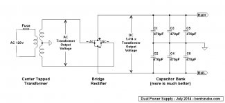
On a totally, absolutely different subject, don't be afraid of dual power supplies. Just FYI I've attached a representative schematic.
.
Power supply overheats, and there's a 120 Hz hum. There's gotta be a fault in the power connections--though that might not be the only fault. Along that line:
I'm all in favor of buying kits, they're a good way to get your feet wet. That remaining so:
The circuit you're using (on the eBay page) has only minor changes from the ST data sheet schematic, which I post below for reference. There's a very good reason for this "only minor changes."
The reason is that chips are not designed in a vacuum. Rather, they're designed to work in a given circuit, which is the one given in the data sheet. Equipment manufacturers down the line might make small or large changes to the original data sheet circuit, but they're always working with that original bedrock circuit because that's how the chip was designed to work, and it doesn't work any other way.
I'm trying to sell you on the idea that the factory circuit works, it always works, it's guaranteed to work, and it's impossible for it not to work. Which leads to the inevitable conclusion.
Lookee, I hate to come in sounding like the all-wise, or Sammy Smartmouth or somobody, but there's just no getting around the fact that you soldered something up wrong. If it makes you feel any better, you're not exactly the first.
The way to fix this is not as bad as it sounds. Start at pin one of the chip and see what's connected. Compare this to what the schematic says should be connected. Then pin two, and on down the line.
Power supply connections, same thing. Ground connections, same thing. I know this sounds like it will take hours, but it really doesn't. It helps to write things down.
That's my say on the subject. But some additional notes:
You can't measure the impedance of speakers without lab equipment. You just have to believe the manufacturer's rating.
Voltage on an amp's output is checked with the input grounded. Zero input should be zero output. You can check with the amp running, of course, but the audio signal that's present screws the readings.
In the attached I've highlighted audio lines in yellow(ish), power lines in red, I thought that might help.
On a totally, absolutely different subject, don't be afraid of dual power supplies. Just FYI I've attached a representative schematic.
.
Attachments
Last edited:
...Availlytics, look more carefully. This is a single supply implementation with capacitor coupled outputs and the heat sinks will be at ground potential.
 oops! Its single supply.
.
I knew there was something I forgot to sound off about. It's been nibbling at me.
<< maybe I need capacitors on the outputs? >>
Ummm...yeah, you kinda do. Capacitors C3 and C4 to be exact, on the eBay schematic. And I greatly hope you didn't blow your expensive-sounding speakers.
You're providing 12 volts to the circuit, but resistors R1-R2, and R7-R8, are a "voltage divider network" that cuts the 12 volts in half (because the resistors are equal) and feeds the resulting 6 volts to the TDA2030 input, pin 1.
The audio signal is also fed to the same pin 1 input, and the result is that the chip receives a total input that's not AC, as is more common, but "modulated DC." That is, what would be a steady 6 volts DC from the power supply is modulated (changed) by the audio signal.
All of which is fine with the TDA2030, but that 6 volts goes right through the amplifier, appearing at the output along with the audio signal.
(Circuit note: capacitors C3 and C8 restrict the circuit's DC gain to one, so the DC voltage is not amplified along with the audio signal.)
This 6 volts DC appearing at the output is now blocked by the output capacitor (C3 or C4), while the audio signal can pass, and feeds through to the speaker.
Or if the output capacitor is missing, then the DC is fed to the speaker also. Not good, speakers don't like DC.
Hope this might be of some interest.
.
Last edited:
post6 shows a 2000uF (2mF) cap acting as aDC blocker and feeding the 8ohms speaker.
Unfortunately the designer has made it into a Filter Capacitor with a turn over frequency of ~ 10Hz.
This will introduce into the output signal.
The Input Filter (DC blocker) is set to a turn over frequency of <2Hz.
If one wants wideband and low distrotion the Output capacitor must be set LOWER than the input capacitor.
You can achieve this by making the 2mF much larger or making the 1uF much smaller.
The Input Filters MUST set the HF and LF bandwidths of the Power Amplifier.
Oops !!! the designer has forgotten about the HF filter. ADD an RF filter as well as getting the LF turn over freqs correct.
C2 set to 2uF is wrong as well. It creates a filter with a turn over of ~17Hz.
Who designed this amplifier?
Last edited:
And it gets worse.
The PSU is no good for a wideband amplifier.
It probably would work as a Treble only amplifier in an active speaker system. It might even work well enough as the Mid driver amplifier.
The 3 470uF caps should be changed to 3 4m7F caps for at least 10mF or better 20mF of smoothing capacitance.
And don't connect the centre tap to the output of the filter bank.
The two wires from the rectifier and the centre tap MUST connect to the INPUT of the filter bank.
.
<< Who designed this amplifier? >>
As it says on the schematic, it's from the SG data sheet. In fact, it's a screen shot (screen capture) of the data sheet, with no changes except the yellow(ish) and red(ish) highlighting I added.
Here ya go: http://pdf.datasheetcatalog.com/datasheet/SGSThomsonMicroelectronics/mXrxxvs.pdf
Thanks for your observations about the power supply. However it is, as I said, representative, not a construction project. Binary star grounds and bypass capacitors are always understood.
.
Last edited:
According to what I have heard, the ST production of TDA2030/2040/2050 stopped around 2013. If we see the ST versions as the originals, hardly any of what is sold today are "originals".
UTC (Unisonic Technologies) seems to produce TDA2030 and TDA2050. You can call them "originals" or "fake" as you like but at least UTC publishes datasheets.
You can still buy TDA2030/2040/2050 from Asia with the ST logo. They will in most cases play but to which specifications?
UTC (Unisonic Technologies) seems to produce TDA2030 and TDA2050. You can call them "originals" or "fake" as you like but at least UTC publishes datasheets.
You can still buy TDA2030/2040/2050 from Asia with the ST logo. They will in most cases play but to which specifications?
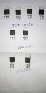
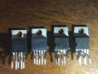
I want to know whether the Tda2030A chips available with me are genuine or fake. Please anyone see the pictures I'm sending as attachment and tell me if they are fake or genuine
ST Tda2030A(100%authentic , pulled from an 10 years old working amp),
ST tda2050(100% authentic , bought 5-6years ago).
Take a look at the legs(ST chips) , they are wider at the top, take a look at that scoop on the side, it is not in the middle.
Now, I am not sure , but do you have an tda2040A? Not such a thing....
Attachments
Friend, you conneted supply voltage 12.6v ac!, it was problem of your amp,because 12.6v ac to dc convert with filtering voltage about 17.6v dc, 17.6 x 2 =35.2v dc, but tda2030a need maximum dc voltage is +14v and -14v,= 28v dc, maximum connected ac voltage is 10v ac, 10 x 1.4= 14v dc, for better and long last working, and need a good heat sink.
- Status
- This old topic is closed. If you want to reopen this topic, contact a moderator using the "Report Post" button.
- Home
- Amplifiers
- Chip Amps
- TDA2030 amp issue help!