Hi everyone,
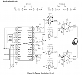
I'm new to this forum and new to audioDIY. Currently, I met a problem of using OPA4132 with PCM1794. I used the typical circuit in the figure, it's from TPA6120 datasheet. I have two questions:
1. What is the function of OPA4132 in this circuit, since TPA6120 has an input impedance of 300k ohm, why we need the OPA4132 as the IV section?
2. What do I expect to observe at -INB and OUTB in the oscilloscope? What I observed is opposite DC voltage but AC signal with the same phase, this seems not right.
Could someone explain the circuit with details, any tips can help?
Attachments
I am non digital so expect a mistake or three, read at your own risk:
the two output signals IoutL- and IoutL+ are current outputs but with opposite phase.
The first two opamps convert the current output into a voltage output (IV conversion).
These two outputs are still of opposite phase.
The last opamp sums the two out of phase signals into a single ended (unbalanced) voltage output.
Repeat for the right channel.
the I/V converter circuits' inputs are "virtual ground" - shouldn't see any (<1mV audio) signal there if the circuit is working correctly
quad op amps are not so popular today - many more parts offered in duals, with surface mount the usual challenge is getting all of the passive parts close enough to the chip - dual op amps are a good compromise with singles used when crosstalk in the package is a concern
quad op amps are not so popular today - many more parts offered in duals, with surface mount the usual challenge is getting all of the passive parts close enough to the chip - dual op amps are a good compromise with singles used when crosstalk in the package is a concern
- Status
- This old topic is closed. If you want to reopen this topic, contact a moderator using the "Report Post" button.