Hello everyone!
I have been a longtime lurker and while I did make my first posts back in Sept of 2012 I have had to shelve my active crossover project for quite some time. It is almost time for me to dust project off and work on it again, and as such I needed to have a simple amp to test it out with.
So I designed a modular 4 channel amp using the TDA7396 chip. The circuit is largely based off of the application circuit for the chip with a few tweaks to suit my purposes. I primarily want to use this in an automotive application, but I will also probably have a use for a few more boards around my APT and parents house.
I will post of the values for the components later, but first I thought I would toss up an image of the PCB to see what people think. While I have hack jobbed several chipamps before; this is my first real attempt at designing something decent (star grounding, etc).
I'm just going to copy my post from DIYmobileaudio
And yes, I originally mislabeled the voltage source as VSS instead of VDD, it has since been fixed.
So what do you think? What have I done well, and what can I improve on?
I have been a longtime lurker and while I did make my first posts back in Sept of 2012 I have had to shelve my active crossover project for quite some time. It is almost time for me to dust project off and work on it again, and as such I needed to have a simple amp to test it out with.
So I designed a modular 4 channel amp using the TDA7396 chip. The circuit is largely based off of the application circuit for the chip with a few tweaks to suit my purposes. I primarily want to use this in an automotive application, but I will also probably have a use for a few more boards around my APT and parents house.
I will post of the values for the components later, but first I thought I would toss up an image of the PCB to see what people think. While I have hack jobbed several chipamps before; this is my first real attempt at designing something decent (star grounding, etc).
I'm just going to copy my post from DIYmobileaudio
And yes, I originally mislabeled the voltage source as VSS instead of VDD, it has since been fixed.
SeaShadow said:Ok so before I begin posting more details, let me just say that:
This work is licensed under a Creative Commons License

That license applies to this entire project. If you want to make your own for personal use, feel free to do so. I will be posting the finished design files when I have my amp built and tested. But this design is published "as is" with no guarantees expressed or implied, etc.
IE build at your own risk, not my fault if you manage to blow up an electrical system, toast some speakers, or create a singularity, etc.
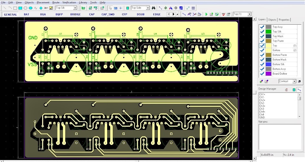
Minimum trace width on the power bus is on the ground plane, linking 3 of the tank caps to the rest of the board, and also helping to shield the signal traces from ambient noise. The narrow point is 175 mils wide and should be good for 11 Amps sustained, granted it is part of the tank circuit, so in all reality the amp should be able to handle way more current than that, with the limiting factor being the voltage supplied.
It should be able to run off anything between 8 and 18 volts (DC), and can drive down to a 2ohm load. Obviously the voltage supplied will determine your power output. That is why I am going to be using that boost module to bump the voltage from my car up to ~18 volts. But in all practicality, supplying 18v vs 12v will only provide 2x the power IE 30 watts RMS vs 15 watts RMS (3dB) with a 4 ohm load.
It is worth noting that the tabs on the TDA7396 are not isolate and are tied to ground. So whatever heatsink you bolt these chips to will also be at ground potential unless you isolate it with a thermal pad of some sort.
Also the Analog ground is tied to the GND pin directly and not via the ground plane, hopefully that reduces the noise in the circuit when the amp is supplied with single ended sources. It is also provided as a pin breakout for the input stage on the input pin-header as pin 1 (the far left).
Pin 2 is the standby switch and is used to connect to the remote line. When powered this will bring the amp chips up to an operational state, when the pin is low it will bring the amp into standby mode, which should be ~.5 mA but that is with out the boost power circuit. I have no idea what the quiescent current is for that module as it has not arrived yet.
Pins 3-10 are the signal pins for the amp, these are paired off (+-) for each channel.
I still need to tweak a few more things and fix some typographical errors in the silk screen, but in essence that is a simple 4 channel amp. I'm going to toss this design before the wizards of DIYaudio and see what they think before I go ahead and order the parts to make a prototype. Once I get it working, I will post the complete design files along with schematic and component values.
So what do you think? What have I done well, and what can I improve on?
DipTrace looks nice: I just tried the freeware version and seems very intuitive as you mentioned. I tried Eagle some time ago but I gave up and reverted to pcb drawing using Adobe Illustrator which I use professionally for other purposes... I'll give DipTrace a chance for my next project.
- Status
- This old topic is closed. If you want to reopen this topic, contact a moderator using the "Report Post" button.