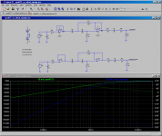
Refer to the attached simulation of a 2nd order high pass filter, the green curve is the result of using the opa627 PSpice model directly downloaded from Texas Instruments today, while the blue curve is the result of using the ideal opamp model.
I can't believe the difference. It is not possible to be that much different. What has gone wrong?
The asc file was created by Keantoken for me a while ago. I think I supplied him the TI downloaded model file, and he digged out a symbol and put it into an asc file for my use. Today I replaced the opa627 model file with the latest version from TI.
The asc file is attached. Unfortunately, I can't attach the MODEL file but you can get it from the TI site.
Regards,
Bill
Attachments
Last edited:
Ummm . . . (mustering up my best "Sophomore Electronics Class" instructor's voice) . . . Which result is closest to what you were EXPECTING to see? Is there anything you readily notice about the difference between your expectations, and the simulation results? Do the answers to these questions provide a clue to the error you are looking for?
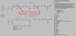
You have a SHORT CIRCUIT between the output of opamp U6 and the output of opamp U7. LENGTHEN IT.
(Probably a careless cut-and-paste error during editing.)
Dale
You have a SHORT CIRCUIT between the output of opamp U6 and the output of opamp U7. LENGTHEN IT.
(Probably a careless cut-and-paste error during editing.)
Dale
Attachments
Dale,
To me
To you
Thank you wholeheartedly
Bill
PS. Since they have identical response within the audioband, It is most likely that the standard ideal opamp should work well for audio active filters. I will check with 20MHz bandwidth though and make sure nothing bad happens at higher frequencies.
To me
To you
Thank you wholeheartedly
Bill
PS. Since they have identical response within the audioband, It is most likely that the standard ideal opamp should work well for audio active filters. I will check with 20MHz bandwidth though and make sure nothing bad happens at higher frequencies.
In exchange for a serving of my favorite malt beverage, you can be certain that your supervisor (or instructor) will never hear of this incident from me.To me
Why are you considering this approach? The LTSpice "simplified opamp" seems to be an accommodation intended primarily for conceptual investigations of an academic or tutorial nature. Its primary advantage is probably execution speed of a simulation, and even that won't be obvious (unless you're running a 486-class machine) for a realistic circuit with fewer than a dozen opamps.PS. Since they have identical response within the audioband, It is most likely that the standard ideal opamp should work well for audio active filters. I will check with 20MHz bandwidth though and make sure nothing bad happens at higher frequencies.
If I had intentions of ever building this as a physical circuit, I'd simulate with the manufacturer's macromodels unless I had a good reason not to. Especially with active filters, even though the end-to-end behavior may appear rather undemanding, there may be things happening internal to the circuit that stress the opamp's capabilities. At the very least I'd want a model that accounted for finite slew rate, output clipping, and input capacitance effects.
As a general group, published opamp macromodels tend to be far short of what they COULD be if manufacturers would make the effort. Significant improvements to the accuracy and completeness of the Boyle/Cohen macromodel were documented and published in the early 1990's at Burr-Brown and Analog Devices but don't seem to have been widely adopted even within those organizations. Even so, a basic Boyle/Cohen model is MUCH more realistic than the LTSpice simplified approximations.
Dale
Dear Dale, the Sophomore Electronics Class Instructor,
You can have as much your favorite malt beverage as you like if you pass Sydney and this is your ticket. If you don't come this way then let me serve you some e-beverage in hope of getting one more free lesson.
Out of the 3 you listed (slew rate, output clipping, and input capacitance effects), I only know how to check output clipping. I think I can also check accurately current draw, power dissipation, or perhaps even rail noise injections, but I don't know how to check slew rate limit, and input capacitance effects.
There are more. For an example, I have been wondering how much compensation is needed for a non-inverting gain stage (cap from Vout to -Vin) to achieve the best transient response, i.e. minimal overshoot or undershoot. Could I simply generate some squire waves at 100kHz from the input and check the output? Or perhaps the marcomodel won't give me this level of accuracy and only a scope can provide the answer?
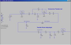
For another example, I would like to know how much isolation resistance is required for capacitive load. Attached is the real (i.e. almost real) circuit I am planning to use. I am learning to design the entire preamp/active crossover, as well as the input stage of the power amp. How would I know if C6 is too big to cause grief to the proceeding opa627, or if C6 can be increased to provide better RF noise suppression for the power amp, as the low pass corner frequency is really too high at the moment?
Of course, I wouldn't expect you to write a book for this lesson but if you could in the briefest way point me in the right direction that would be very much appreciated.
Regards,
Bill
You can have as much your favorite malt beverage as you like if you pass Sydney and this is your ticket. If you don't come this way then let me serve you some e-beverage
in hope of getting one more free lesson. Out of the 3 you listed (slew rate, output clipping, and input capacitance effects), I only know how to check output clipping. I think I can also check accurately current draw, power dissipation, or perhaps even rail noise injections, but I don't know how to check slew rate limit, and input capacitance effects.
There are more. For an example, I have been wondering how much compensation is needed for a non-inverting gain stage (cap from Vout to -Vin) to achieve the best transient response, i.e. minimal overshoot or undershoot. Could I simply generate some squire waves at 100kHz from the input and check the output? Or perhaps the marcomodel won't give me this level of accuracy and only a scope can provide the answer?
For another example, I would like to know how much isolation resistance is required for capacitive load. Attached is the real (i.e. almost real) circuit I am planning to use. I am learning to design the entire preamp/active crossover, as well as the input stage of the power amp. How would I know if C6 is too big to cause grief to the proceeding opa627, or if C6 can be increased to provide better RF noise suppression for the power amp, as the low pass corner frequency is really too high at the moment?
Of course, I wouldn't expect you to write a book for this lesson but if you could in the briefest way point me in the right direction that would be very much appreciated.
Regards,
Bill
Attachments


Of course, your ability to find any performance shortcoming related to a device imperfection, and compensate or correct it, using simulation will depend on the completeness and accuracy of the simulation models. Some of the limitations of modeling techniques are discussed in the tutorial "Analog Circuit Simulation" at http://www.analog.com/static/imported-files/tutorials/MT-099.pdf and especially Analog Devices' Application Note AN138, "SPICE-Compatible Op Amp Macro-Models" at
http://www.analog.com/static/imported-files/application_notes/AN-138.pdf . (Similar App Notes from Burr Brown are "Operational Amplifier Macromodels: A Comparison" at http://www.ti.com/lit/an/sboa027/sboa027.pdf and "SPICE Based Macromodels" at http://www.ti.com/lit/an/sbfa009/sbfa009.pdf .)
If you have confidence in the model's ability to accurately model slew rate, it may be easier to simulate with the worst-case input signal, and also with the same signal at lower amplitude (say, 1/10 the voltage). Then use the LTSpice trace math to scale and superimpose the two signals.
Input capacitance effects show up as perturbations in frequency response, peaking near the amplifier's upper cutoff frequency. How this affects overall circuit performance depends on topology and how close you're working to the opamp's capabilities. The algebra may appear formidable but the graphics in TI App Note SLOA013A "Effect of Parasitic Capacitance in Op Amp Circuits" at http://www.ti.com/lit/an/sloa013a/sloa013a.pdf give a general idea of what's happening.
Dale
http://www.analog.com/static/imported-files/application_notes/AN-138.pdf . (Similar App Notes from Burr Brown are "Operational Amplifier Macromodels: A Comparison" at http://www.ti.com/lit/an/sboa027/sboa027.pdf and "SPICE Based Macromodels" at http://www.ti.com/lit/an/sbfa009/sbfa009.pdf .)
The original Boyle model topology was especially weak at modeling anything related to the power supplies. See the Analog Devices AN-138.Out of the 3 you listed (slew rate, output clipping, and input capacitance effects), I only know how to check output clipping. I think I can also check accurately current draw, power dissipation, or perhaps even rail noise injections . . .
For slew rate, I'd apply the worst case input signal (highest frequency, highest amplitude) and look directly at the outputs of each individual opamp. If the simulation shows a slew rate faster than, say, half the opamp's data sheet value (or some other reasonable design margin) I would rework the design. (Usually, this approach can be used whether the model accurately accounts for slew rate or not.). . . I don't know how to check slew rate limit, and input capacitance effects.
If you have confidence in the model's ability to accurately model slew rate, it may be easier to simulate with the worst-case input signal, and also with the same signal at lower amplitude (say, 1/10 the voltage). Then use the LTSpice trace math to scale and superimpose the two signals.
Input capacitance effects show up as perturbations in frequency response, peaking near the amplifier's upper cutoff frequency. How this affects overall circuit performance depends on topology and how close you're working to the opamp's capabilities. The algebra may appear formidable but the graphics in TI App Note SLOA013A "Effect of Parasitic Capacitance in Op Amp Circuits" at http://www.ti.com/lit/an/sloa013a/sloa013a.pdf give a general idea of what's happening.
This is one area where simulation should be quite useful. If the transient response is affected by output loading it will depend on the accuracy of the model's output section. The A-D MT-099 tutorial demonstrates this on page 7, and pages 11-12.There are more. For an example, I have been wondering how much compensation is needed for a non-inverting gain stage (cap from Vout to -Vin) to achieve the best transient response, i.e. minimal overshoot or undershoot. Could I simply generate some squire waves at 100kHz from the input and check the output? Or perhaps the marcomodel won't give me this level of accuracy and only a scope can provide the answer?
Many opamp data sheets give good guidelines on this. (The OPA627 data sheet seems to suggest that 20 ohms is adequate. See Fig 6.) TI App Note SLOA013A discusses this with greater theoretical analysis in Section 6.For another example, I would like to know how much isolation resistance is required for capacitive load. Attached is the real (i.e. almost real) circuit I am planning to use. I am learning to design the entire preamp/active crossover, as well as the input stage of the power amp. How would I know if C6 is too big to cause grief to the proceeding opa627, or if C6 can be increased . . .
Dale
Dale,
Your posts have been very much appreciated. For capacitance at the input or output of an opamp, I think I can follow the TI App Note SLOA013A closely. I should be able to get good result by doing that without relying on simulations. For the rest, it is always a good idea to use the macromodel, feed the opamp with maximum input voltage at the highest possible frequencies the opamps needs to deal with, and with fast rise time and check the results.
Regards,
Bill
- Status
- This old topic is closed. If you want to reopen this topic, contact a moderator using the "Report Post" button.
- Home
- Amplifiers
- Chip Amps
- opa627 Spice Model vs Ideal Opamp Model