Hi, Joe,
We haven't corresponded in some time, so I just thought I would drop in here to say hello. I hope all is well with you and your family.
I see from your Custom Analogue website that you are still developing unique approaches to obtaining good sound. I check the site from time-to-time to see what new ideas you are currently about. I've always appreciated your rejection of rigidly doctrinaire thinking, which, as you well know, entails enduring slings-and-arrows from the self-righteous, who, with minds closed, reflexively defend orthodoxy.
Hi Ken
Thank you. Great to hear from you, just gotten back from a short holiday break, visiting windy Tasmania.
Take a look at this:
Local feedback, about 20dB. This kind of feedback works in real-time unlike NFB. The coupling caps is not shown as I want the focus to be on those resistors and what they do. Note that the input Grids act near 'virtual earth' as the voltage drops from 10V RMS to 1.1V RMS. The input impedance is a high 150K and does it not look a little bit like an I/V converter?
The output tap is 8 Ohm, so the whole thing has a negative gain -24.4dB and hence the challenge is that it needs a driver that can swing massive amounts of voltage. Do the maths and you need to swing more than 900V peak-to-peak. Designed such a front-end that does just that, indeed if the PS voltage is available, can swing up to 1800V peak-to-peak:
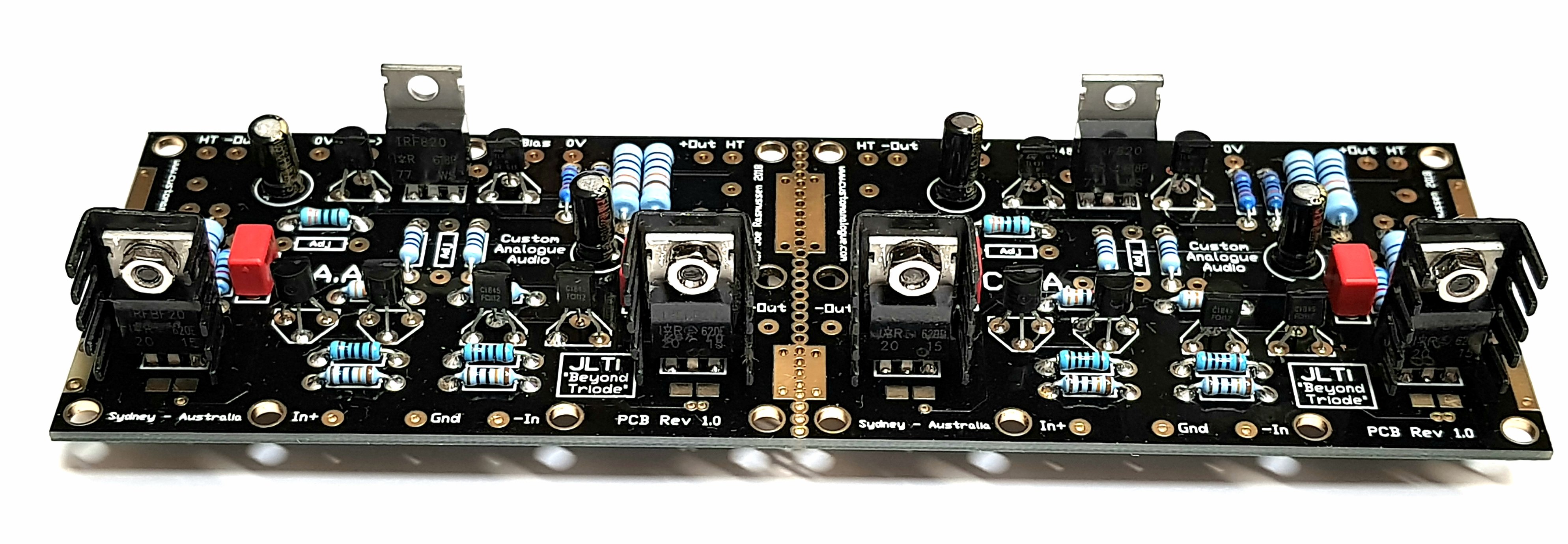
You have probably seen that PCB on my website.
Note to Moderator, this is not off topic (which was started by me in the first place), as the topic is about the current in amplifiers and speakers, and how they interact. I built the transconductance amplifier as part of my work (some would call it research) in exploring these things. I then shared this simple design because when used right, it sounds surprisingly good.
So Ken, this new (dangerous word these days) amplifier is all about the current. Even that front-end is about current, the input stage converts the source voltage to current, then the 900V Power MosFets are driven via their Sources as the inputs. There is absolutely zero voltage swing on the Gate that is normally used as input, so the non-linear capacitance there has no effect. I was very lucky, through a personal contact I was able to get the circuit computer modelled by one of the world's best, the head of Power Electronics, part of SpaceX. He actually designs the guidance systems in Elon Musk's rockets, indeed Musk's right-hand electronics guy. I can't give you his name here, only via PM and in confidence. Unbelievable linear, ultra-low distortion.
If you haven't seen it yet, go to my Facebook page for more info there, just go back into the past a few years.
Joe Rasmussen | Facebook
The overall circuit is very configurable and highly changeable sound wise. It took me a long time to figure things out. Just looking at the schematic does not tell the whole story and also not shown the Power Supply that was quite challenging to get it right. I am 68 today (I don't celebrate birthdays) and in my life this has been the single largest project and really only finished last month. Started in October 2016 and I was pushed into it by Brian Gurr in Auckland, New Zealand, when I was visiting. Brian was also a friend of the late Allen Wright.
I am working with a group that is looking into how amplifiers react with speakers on the current side, because we now know that so many things are either taken for granted or just put away as too hard and not so important. Maybe also because we have all been a bit lazy in the past, and I include myself.
I will be doing some measurements soon that will show distortion on the current of an amplifier that does not show up on the voltage side. A crude measurement has already been done, but needs to be done more critically and documented right, as well as capturing the distortion on the acoustic side of the speaker. I have about twenty people that the results will be shared with and we will have a private discussion online where the trolls cannot shout it down with noise.
Keep in touch if you have an interest in the above. My email address is publically known joeras@customanalogue.com and I trust you, so I can fill you in on those measurements.
Cheers, Joe
JOE Update your picture link on page One.
Done!
The "http://" had to be changed to "https://"
JOE Nope... does not work...
You may need to use the refresh button or else it will just reload that page out of the cache.
I have repeated it here:
Last edited:

Local and negative feedback are not opposites, negative feedback can be local or global (and can be shunt or series), and is real-time in all cases. Any kind of a delay element in a negative feedback network is bad news for stability as this reduces phase margin directly.
Hi Dave, hope you are doing well.
It certainly has caused me grief. It seems that I have a website that responds to both http and https, should I get in touch with my provider and tell them to get rid of http? Maybe that is causing a problem?
Where I am, using https for images is working. But elsewhere, in some places, it is not?
This is the old http:
Joe Rasmussen Pages
This is thhe https:
Joe Rasmussen Pages
Right here in Sydney, both links work. Is that a cause for problems?
Cheers, Joe
Edit: I have, as much as possible, been using https, correcting old and only using https for new images and posts.
The worldwide change to all https: has caused some grief.
dave
diyAudio moderation team
It certainly has caused me grief. It seems that I have a website that responds to both http and https, should I get in touch with my provider and tell them to get rid of http? Maybe that is causing a problem?
Where I am, using https for images is working. But elsewhere, in some places, it is not?
This is the old http:
Joe Rasmussen Pages
This is thhe https:
Joe Rasmussen Pages
Right here in Sydney, both links work. Is that a cause for problems?
Cheers, Joe
Edit: I have, as much as possible, been using https, correcting old and only using https for new images and posts.
The problem may be not https but something else.
This is where the actual Gif graphic file is stored on my website and this is what is used when I upload it in a message:
"https://www.customanalogue.com/diy/Trans_Amp_Schema_Wiring_Caution.gif"
Copy and paste the URL address and you have direct access to it. How diyaudio.com deals with this is beyond my control, does the graphic get stored elsewhere (on a Dutch .nl website?)?
Yes.Hi Ken
You have probably seen that PCB on my website.
")
I, too, am a fan of the grounded-gate. As you know, it's very common in RF applications, but is rarely used in audio (except as a cascode, of course).So Ken, this new (dangerous word these days) amplifier is all about the current. Even that front-end is about current, the input stage converts the source voltage to current, then the 900V Power MosFets are driven via their Sources as the inputs. There is absolutely zero voltage swing on the Gate that is normally used as input, so the non-linear capacitance there has no effect.
You are very fortunate to have access to leading-edge engineering talent like that. Does this gentleman also happen to be an audio enthusiast?I was very lucky, through a personal contact I was able to get the circuit computer modeled by one of the world's best, the head of Power Electronics, part of SpaceX. He actually designs the guidance systems in Elon Musk's rockets, indeed Musk's right-hand electronics guy.
Happy Birthday, just the same!I am 68 today (I don't celebrate birthdays) and in my life this has been the single largest project and really only finished last month.
I'm naturally curious and attracted to new ideas, so, yes, I'd be interested in being apprised of intriguing breaking developments.I will be doing some measurements soon that will show distortion on the current of an amplifier that does not show up on the voltage side. A crude measurement has already been done, but needs to be done more critically and documented right, as well as capturing the distortion on the acoustic side of the speaker. I have about twenty people that the results will be shared with and we will have a private discussion online where the trolls cannot shout it down with noise.
Keep in touch if you have an interest in the above. My email address is publically known joeras@customanalogue.com and I trust you, so I can fill you in on those measurements.
Cheers, Joe
Off topic. I'm curious about your perspective on volume controls, about your preferred form/implementation. There are so many differing approaches, and I don't recall reading your thinking about it. I'm currently working on an DIY preamp and would value your input about this. I don't want to hijack this thread, so, perhaps, PM me, or point me to any prior published comments of yours about this, if that's not too inconvenient. Thanks, Joe.
Last edited:
Hi Ken
Sorry, been busy putting finishing touches on the new amp. I will now find out just how good it is, having put some into certain hands for honest feedback.
Not an RF guy, but not hard to understand it works with RF.
No, but his Dad is and that is how I was able to make the connection.
This one will scramble your brains because it tries to make you think in a very different way. But I have good support and encouragement. This is a subject that I believe has found its time. So hopefully fairly soon I will get back to you.
A most vexing topic.
These days I use the volume control in the Sabre DAC and I find it really excellent. They knew what they were doing here.
Around 15 years ago I posted somewhere on diyaudio.com about this tiny little pot, mechanically not the strongest and not 1/4" shaft:
Uses silver-carbon, sounds very neutral and difficult to fault, other than they can have a bit of a short life - depends how they are treated.
I tried to find that 2004 thread... ?
50k Ohm Logarithmic (A) Double Gang 9mm Potentiometer | Jaycar Electronics
Cheers, Joe
Sorry, been busy putting finishing touches on the new amp. I will now find out just how good it is, having put some into certain hands for honest feedback.
I, too, am a fan of the grounded-gate. As you know, it's very common in RF applications...
Not an RF guy, but not hard to understand it works with RF.
You are very fortunate to have access to leading-edge engineering talent like that. Does this gentleman also happen to be an audio enthusiast?
No, but his Dad is and that is how I was able to make the connection.
I'm naturally curious and attracted to new ideas, so, yes, I'd be interested in being apprised of intriguing breaking developments.
This one will scramble your brains because it tries to make you think in a very different way. But I have good support and encouragement. This is a subject that I believe has found its time. So hopefully fairly soon I will get back to you.
Off topic. I'm curious about your perspective on volume controls, about your preferred form/implementation. There are so many differing approaches, and I don't recall reading your thinking about it. I'm currently working on an DIY preamp and would value your input about this. I don't want to hijack this thread, so, perhaps, PM me, or point me to any prior published comments of yours about this, if that's not too inconvenient. Thanks, Joe.
A most vexing topic.
These days I use the volume control in the Sabre DAC and I find it really excellent. They knew what they were doing here.
Around 15 years ago I posted somewhere on diyaudio.com about this tiny little pot, mechanically not the strongest and not 1/4" shaft:
An externally hosted image should be here but it was not working when we last tested it.
Uses silver-carbon, sounds very neutral and difficult to fault, other than they can have a bit of a short life - depends how they are treated.
I tried to find that 2004 thread... ?
50k Ohm Logarithmic (A) Double Gang 9mm Potentiometer | Jaycar Electronics
Cheers, Joe
A most vexing topic.
Uses silver-carbon, sounds very neutral and difficult to fault, other than they can have a bit of a short life - depends how they are treated.
I tried to find that 2004 thread... ?
50k Ohm Logarithmic (A) Double Gang 9mm Potentiometer | Jaycar Electronics
Cheers, Joe
Silver-carbon? Interesting, that's a pot. composition description which I haven't seen before. I assume this is distinctly different from the track material composition utilized in typical carbon potentiometers?
Silver-carbon? Interesting, that's a pot. composition description which I haven't seen before. I assume this is distinctly different from the track material composition utilized in typical carbon potentiometers?
Yes, quite different.
https://www.diyaudio.com/forums/chip-amps/40676-try-potentiometers-21.html#post528282
Read Post #202 by KT and mine #203.
EDIT: I found the thread:
Pot ex Tawan - Photo - ignore my ugly Pinky!
Joe,
Thanks, those those detailed reposnses. Do you know whether the silver-carbon composition is standard for an Alpha pot., or is it instead some specially produced unit from them?
Hi Ken
It has been such a long time ago, but I remember seeing the pot for sale by Jaycar (I used to do some testing consultancy for the ower of the company) and it took a lot of digging and find it on a less than obvious part of Alpha's website. Not remembering the exact words, but something about carbon "substrate" containing silver. So I bought one and tried it - and it was the best "pot" I had ever heard, clean and no obvious colourations.
I have now used about a hundred of them. I test them for channel balance before I use them. But over that 15 year period I have had to replace some, they are mechanically not the strongest and they can go noisy - I don't think the like DC from. say, grid-leak current from a tube. So if you have a bad input tube and measured mV there.
- Home
- Amplifiers
- Chip Amps
- Joe Rasmussen "Trans-Amp" - 40 Watt Transconductance "Current Amplifier"