Change in excess noise level and change in excess noise spectrum...that 0.33R resistor is mission critical as is the excess noise contribution of the carbon resistors.Well I played around with different components (this same circuit) and each time the components made a substantial difference, some more noticeable than others -
For the first attempt (Verobrd) I used Zfoil Vishays for the input (a bit 'full of myself here!) some Takman and Phillips metal film resistors and the input cap was a Wima mkp10 and the 1n5 and 100nF were some Rifa pfe216 styrene - that 0R33 was a power Caddock met film - diodes were BYW29 (not the smoothest ones!) - power caps were Nichicon GoldTones - the sound was rather bright in my system and also in the AKG k701's but plenty of 'punch' and a but deficient in the bass - too much treble after awhile, annoying.
Number 2 went the other way - carbon resistors (mostly kawame, ABradley, etc) and the 0R33 was a handmade from Manganin resistance wire - input cap was an Audiophiler, the 1n5 & 100nF were Vishay PP, diodes MBR860 and Mundorf power caps - the sound was very 'laid back' in comparison - a bit dull actually - rather surprised.
Excess noise causes masking and modulations/intermodulations, the result can sound 'nice' or decidedly 'not nice' according to the materials involved.
Manganin is a trademarked name for an alloy of typically 86% copper, 12% manganese, and 2% nickel. It was first developed by Edward Weston in 1892, improving upon his Constantan (1887). A resistance alloy with moderate resistivity and low temperature coefficent.
An interesting experiment would be to swap the current sense Manganin R with Constantan R.Constantan is a copper–nickel alloy also known as Eureka, Advance, and Ferry. It usually consists of 55% copper and 45% nickel. Its main feature is its resistivity, which is constant over a wide range of temperatures. Other alloys with similarly low temperature coefficients are known, such as Manganin (Cu86Mn12Ni2).
Dan.
Excess noise causes masking and modulations/intermodulations, the result can sound 'nice' or decidedly 'not nice' according to the materials involved.
Hi Dan, it's been a while. Mine definitely sound good, so I must have done something right?
I think I used three Dales CW-5 1R 6.5W resistors in parallel =0R333, no inductance.
Cheers, Joe.
PS: Sounds way better than whenLM3875 is used conventionally.
Last edited:
The guys of the HK audio club developed a pcb for a 2 channel amp and found it far better than my vero board unit - it is quite dependent on the way it's laid out - Tom Christianson did quite a detailed development around this (see the Neurochrome site)
I have also quite a bit of the wire known as Isotan that is another name for the Constantan - there used to be a lot of the old Isabellenhutte wire on Ebay from Russia and this is a lot 'smoother' than the current production Isotan wire from China
It's quite hard to get the IsabH production power resistors themselves unfortunately but the 1/4W ones from Rhopoint have a similar characteristic - some of these are available from RS and Farnell, but generally silly prices - I got a surprisingly improved detail using that little ldr 'resistor replacer' circuit of Uriah Daley's on the input signal line - a neat little pcb.
I find the Isotan/Constantan to be quite bright and don't use it much and didn't try it in the T40 but have tried it as the source resistors of the F5 amp with similar 'too bright' result - the Nickel certainly brings out the extra top end detail if required
Enjoying the Hoppman cup this week?
So a normal woofer could be sufficiently damped with socks to get close to meeting Joe's flat impedance criteria?
If you effectively EQ the current, then you can drive it with any impedance - in a sort of way, the amplifier disappears. That is a dangerous thing to say, so I will modify it to say, that the amplifiers output impedance seems to disappear. There will be no lack of damping, it will be identical.
Hi all
I've been very interested in this thread as the whole constant current thing makes a lot of sense although I'm used to using it in stepper motor drivers
As I had all the bits to hand, I've built up adason's version of the circuit. The only change is that I used a pair of 0.15ohm resistors as the R7 to give 0.3ohm.
It worked first time into a dummy load so I then wired it into one of my CSS FR125 based minOnkens. The DC offset with 50 ohm across the input terminals is just 33mV. Absolutely no background hum or other noise and loads of power. The tiny heatsink gets hot but not over-the-top at normal listening levels
Power supply is a 12-0-12 100VA toroid with 20,000uF on each rail giving 34V across VEE-VCC on the chip.
It really is remarkably good even given the veroboard construction. My memory of valve amps is very old but is certainly seems to have a very open "big room" sound.
The only change I need to make is to reduce the gain a bit. Did we get a conclusion on the best way to do this? Once I properly understand this I'll make a second channel.
Thanks to Joe and adason for prompting a fun couple of hours of experimentation.
I'm very interested to get Dave's (planet10) view of using a constant current amp for the minOnken.
Peter
I too have been interested since reading about Nelson Pass' F2. I decided to make a pcb to try the concept before building a class A living room heater.
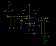
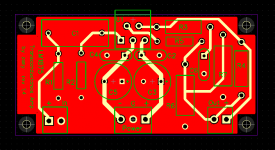
 Below are the schematic and pcb layout. Being a noob at all this electronics theory and pcb routing, there has been a lot of back and forth with design of the pcb to get to a decent layout and routing. This iteration of the board has a ground plane on the bottom side. The dc offset connected to a cheap full range driver is 37 mV. The amp sounds very easy on the ear driving a prototype hybrid active minidsp/passive crossover open baffle speaker + subwoofer system - one channel at this stage. The only thing that I need to correct is the buzz coming from the speaker which I can hear from the listening position during quiet passages (4 meters away). Wondering whether the buzz is coming from the layout of my pcb or from elsewhere? All ideas welcome.
Attachments
I too have been interested since reading about Nelson Pass' F2. I decided to make a pcb to try the concept before building a class A living room heater.
Hi Zany: I built the same schematic for TDA2050 with excellent result. Also had hum elevated. I changed values from R3 to 10R (or 15R) and C6 to 47 nF. I also removed ground from this filter and connected it directly to R6+R7 (by Mr. Rasmussen). Congratulations on the amp, well organized and your audio has a big difference compared to standard amplifiers. I do not understand how the industry and enthusiasts build so few transconductance devices.
Thank you for the kind words augustoriodosul. Your comments regarding transconductance amps are interesting - the open baffle dipole speaker has been up and running for about a month now using an old Rotel 30W integrated amplifier temporarily to tune the active crossover. It took a good amount of work to get it to sound reasonable. This trans amp just sounds so much better - it just sounds right. A big step up in quality. I will test your suggestions. Thanks again.
It's surprising just how good a sound you can get from these little packages if you get it right - I read on the Neurochrome site that connecting the components related to the speaker return and specific pcb layout with regard to ground points can produce quite significant benefits
So, looking at the pcb from this 'point-of-view' I would put the R6 and R7 together either on top of each other or one on the other side of the board (or simply just use one 5W resistor instead) and connect C6 directly to the junction of R5, R6//R7 (as mentioned) and this could be called the new 'ground point 1'.
I would then move the ground connection of both R1 and R2 to this new 'ground point 1' (a wire link, or just use the resistor leads) so these resistors don't have a top layer connection anymore
Then, I'd reverse the bypass caps C2, C4 so they have a common ground point between the electro caps C3 and C5- this keeps all the high currents circulating only around this group of caps and the Chip pins
Now, the overall ground point?
If we are to follow on from Tom Christianson's ideas (see the Neurochrome website), the speaker return would be connected to this new 'ground point 1' (not to the centre pin of the 3 way terminal) and then this point would be linked to the middle pin of the 3 way terminal that's connected to the external power supply 0 volt.
It sounds like a lot of 'nit picking' but separating the ground return currents can be extremely effective for improving performance
... just my 2 cents
It's surprising just how good a sound you can get from these little packages if you get it right ...
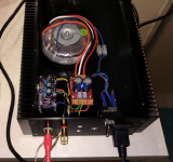
would you mind sending picture with detailed connections? This will be helpful for many people.
I'm still trying to work out how to add photos and things on this site but all isn't lost as the guys in the HK Audio Club did a really well-organised pcb design and I'll see where I stored the information and/or a copy of that - that's probably a lot easier than me mumbling around about which goes where
The way I look at it isn't very different to Joe setup diagram except for the speaker connections and how the ground connections are grouped together - it's the pcb layout where you can lose a lot of the performance - IMO, I hasten to add
Also, it's quite reasonable that someone else has found a better way of doing this as following the Neurochrome design ideas for a voltage gain circuit may not work in the same way as Joe's current gain/transconductance arrangement - I think it will, but it's good to keep an open mind about this rather different way of doing things.
Oh, might add that I have some reservations about just using any old diodes and a couple of electro caps and using that as the power supply so I used some BYV29 soft recovery diodes on the bridge, some Elna for Audio 12,000uF/63v caps then fed it thru Rod Elliot's transistor C-Multiplier and found this improved the sound of this little gem quite a lot
I'm just saying that a bit more effort on the power supply does make a difference despite all the 'yak' about the chip's very high PSRR levels and so on - again, IMO.
- Home
- Amplifiers
- Chip Amps
- Joe Rasmussen "Trans-Amp" - 40 Watt Transconductance "Current Amplifier"