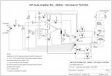
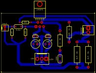
Here is one similar approach published in 2012, not exactly transconductance amplifier but similar in a way of wiring in order to reduce DC offset as some components in input/FB stage are removed in order to get better performance.
Wiring is very very import and need to keep it as shown on schematic.
Same rules apply and for Joe's version.
More info about this design here (use Google translate):
HQ modifikacija za TDA7294 – HiFi Audio Amplifier 5Hz – 200Khz YU3MA
Wiring is very very import and need to keep it as shown on schematic.
Same rules apply and for Joe's version.
More info about this design here (use Google translate):
HQ modifikacija za TDA7294 – HiFi Audio Amplifier 5Hz – 200Khz YU3MA
Attachments
this amp compatible with markaudio 12 P
I have ordered the Lm 3875 chip .
I attached the spec for my speaker.
Is this speaker compatible ?
Do I need a dc detection relay in the out put ?
What is the range of input Voltage power that will work without changing other part value ?
thanks
kp93300
I have ordered the Lm 3875 chip .
I attached the spec for my speaker.
Is this speaker compatible ?
Do I need a dc detection relay in the out put ?
What is the range of input Voltage power that will work without changing other part value ?
thanks
kp93300
Attachments
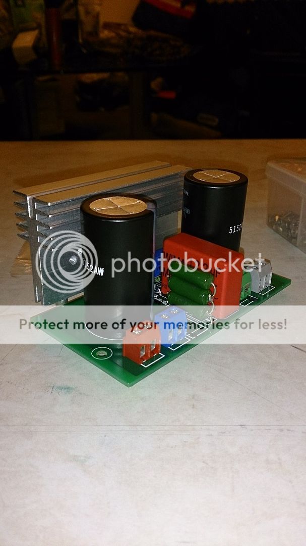
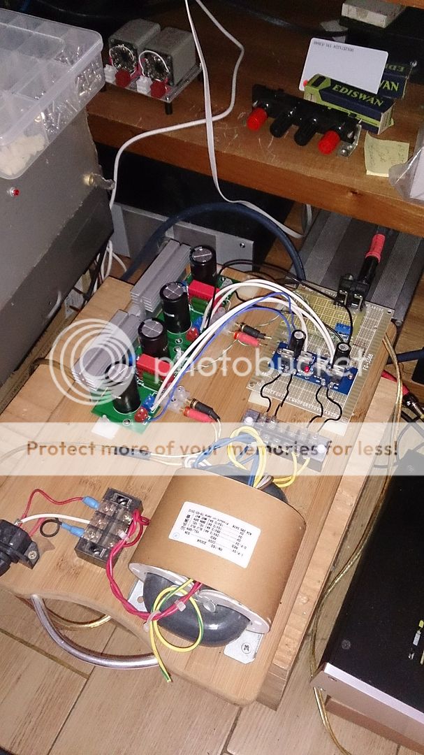
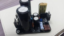
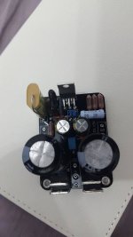
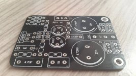
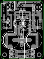
My friend had the PCB made for us to experience this current amp, I am using the Power supply board from PD's chipamp with a 300VA 26VAC x 2 R-core transformer and it is working nicely. I have been using it to drive a pair of the CHN70 for 2 weeks already and it sounded much better than my class D amp. No speaker protection yet, I don't think it is needed, no power on/off pop.
Attachments
Yu,
all the Signal wiring should not be taken to that star type Power Ground.
Absolutely. I noticed that straight away.
.
The original design looks like something I'll have to try since I have LM1875 and LM3875 chips laying around. Back in the day I turned both of them into power instrumentation amps and they sounded great both single ended and when bridged.
This got me thinking about a differential transconductance amp (or even instrumentation amp if you add a couple buffers up front). This also allows for the option of a grounded load because of the two feedback networks. I threw together a quick simulation with an LT1001 op amp in LT spice just to make sure it actually worked. Of course it would need to be tweaked to work with the LM chips, but it's an interesting concept. The grounded load version could in theory be bridged, but everything would be need to be very well matched or the two would fight each other over the output current.
This got me thinking about a differential transconductance amp (or even instrumentation amp if you add a couple buffers up front). This also allows for the option of a grounded load because of the two feedback networks. I threw together a quick simulation with an LT1001 op amp in LT spice just to make sure it actually worked. Of course it would need to be tweaked to work with the LM chips, but it's an interesting concept. The grounded load version could in theory be bridged, but everything would be need to be very well matched or the two would fight each other over the output current.
Attachments
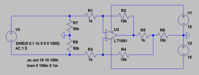
I looked into this design a bit more and completely forgot that it is an "Improved Howland" current pump. This app note from TI does a nice job of explaining things: http://www.ti.com/lit/an/snoa474a/snoa474a.pdf
Still seems like it would be worth a try.
Still seems like it would be worth a try.
Go for it, and then post it here - or start a thread.
Here in Oz we are thinking about starting a research project that looks at current distortion versus voltage distortion in voice coils/dynamic drivers - and basically the damage that crossovers do. We did a loudspeaker with a standard electrical 3rd order, acoustic LR4 crossover, then changed to a crossover with very low current phase angle, just like a current amplifier can only deliver current with a near zero degree phase angle. The difference between the two crossovers were dramatic - it was the same speaker in both cases. One boring and the other alive and engaging. So the current through the voice coil must be as uncontaminated as possible because it is only linear current that makes a dynamic loudspeaker work properly - it must track the current, not voltage.
There is pretty much zero proper research out there - and we have a small group here who wants to correct that. Part of the research will include this 40 Watt amplifier described on this thread. It is designed to be put to work.
")
Cheers, Joe
.
Thank You Joe for the detailed informations. Nelson Pass connects the transconductance amp with fullrange drivers. Is there a logical reason ? I would like to use your amp with a conventional 3-way speaker and an active crossover. What kind of drivers are suited, can the enclosure be calculated as usual, are there other changes except Qes ( set to 1000) ? Your schematic looks really good and simple.
Nelson Pass connects the transconductance amp with fullrange drivers. Is there a logical reason ? I would like to use your amp with a conventional 3-way speaker and an active crossover...
I would not recommend that, as Dave says:
Passive crossovers are often the enemy of current amps. If you go active then your biggest worry is now the resonant peak in the bass -- one could XO low and use a voltage amp there if you can't cure that resonant impedance bump.
dave
The Elsinores from Mk5 onward (current is Mk6) are the only speaker designs with crossovers published that are capable of doing this. Yes, I could be accused of big-noting myself as I am the designer and the only designer who has done this, but it is an accurate statement. Indeed building this 40 Watt design as per this thread, the very reason for designing this amp was to prove it to a few people who effectively accused me of being a liar. It was also to disprove the notion of "Damping Factor" as a complete myth. And I got that from speaking with non other that Richard Small (as in Thiele Small) way back in 1975 who mocked the idea and basically stated that an alignment can work with any source impedance provided that Re (the total series DC resistance) was adjusted. For example if Re of the driver was 6 Ohm and you added a 6R series resistor, then adjust Re to 12R and design your alignment and use the equations (and plotting) using that amended Re = 12. If you do that and you can find a well-damped alignment with the chosen driver, then hey, the fact that "Damping Factor" is only one means nought.
But when you use a current amplifier, then you end up with less than one (negative?) Damping Factor. Well, not quite.
Let's say you have an 8 Ohm speaker and you are driving it with a current amplifier with a source impedance of 240 Ohm, then what is the Damping Factor? It is either 0.0333 or -30 (minus 30), well this is just being silly with numbers. Damping Factor is nonsense and one of the two guys who came up with the numbers treated the idea with total disdain. Good enough for me.
As Dave indicate, the resonant peak in the bass and the crossovers, they are all working while dependent on being driven from a voltage source (low impedance) and just won't work when driven from a current source.
The crossover will not track, especially the Tweeter becomes hopeless exposed. You will get a large boost in the crossover region and the Tweeter will typically be boosted by 10dB.
What the Elsinores do is to equalise (EQ) the current and keep it to a zero degree phase angle, and then something remarkable happens. I won't describe in detail yet, but look at the two plots below
The Red has the EQ and the Green does not.
Red is zero Ohm and Green is 240 Ohm.
One will simply not work (and likely to sustain damage) and the other works very well with both current and voltage sources, indeed that means it works with any source impedance.
Cheers, Joe
.
Last edited:
Let's take it a step futher, again using 240 Ohm as the source impedance versus near zero impedance that is "current" versus "voltage" sources.
This is the Elsinore Mk6 driven by a "voltage" source or zero Ohm impedance:
Now compare this with the Elsinore Mk6 now being driven by a "current" source, which is 240 Ohm:
Look very carefully - they are NOT the same. But both bass alignment and the crossover hold together quite well.
Can we see that both the bass alignment AND the Crossover still tracks quite well, irrespective of the source impedance, right.
Now let stay with 240 Ohm drive, but this time take away the current EQ that Mk6 normally uses:
Again, this is 240 Ohm "current" source.
Both the bass alignment and the crossover are now no longer 'tracking'.
Now we can see what Dave was alluding to so briefly but quite accurately, that BOTH the bass alignment AND the Crossover have gone out of wack.
We can also now see just how horribly the Tweeter is now exposed, would produce dramatic distortion and possibly get damaged very quickly.
Why go through all of the above?
Because this 40 Watt amplifier described on this thread was designed to prove the Elsinores could be driven by an amplifier of any source impedance AND that so-called Damping Factor is a myth.
Not soon after I have made this amplifier work, I had a certain Adam (a very well known person in the Sydney audiophile scene and former owner of a North Shore high-end shop) come over. Adam has been preaching "Damping Factor" to me for more than twenty years - and I simply could not persuade him that it was a fallacy. So when I asked Adam to listen while driving the Elsinores from an amplifier with a source impedance of over 200, I asked him if there would be any damping factor at all - and of course he said correctly "there won't be any" - then I proceded to play at concert level the live recording of Marilyn Mazur on drums and the Joe Morello extended Take Five drum solo, both recordings that are absolutely explosive, with transients that hits you in the guts and also hearing incredibly detailed tunings of the drum sets and the subtlest shifts in dynamic shadings etc. I then asked Adam if he still believed there was such a thing as 'Damping Factor' and he did not answer me straight, but simply said sheepishly "how have the gotten away with it?" Adam KNEW with certainty I had made the point and now we are BOTH in agreement.
Hope the above has been interesting to any of you guys...?
Cheers, Joe
.
Last edited:
Thank you Joe for the great explanation and comparative graphs.
Current loudspeaker drive first piqued my interest when I read Esa Merilainen's book "Current driving of loudspeakers, remedy to the fundamental fallacy of sound reproduction technology" and have been trying to better understand the concept ever since.
The catch in my case is that I'm interested in drivig full-range drivers with a current amp and even got all the components to build the design you presented at the beginning of this thread, but haven't gotten around to build it yet.
So my question is, is it a hopeless quest to desogn enclosures for full range speakers that work well with current amplifiers or is there a way to do it?
Furthermore, full range drivers exhibit a rising impedance with rising frequencies, in which case, a current amplifier would tend to emphasize these higher frequencies, in which case, one should either choose a driver with a falling higher end or EQ it out.. is that a right assumption?
Regards,
Nick
So my question is, is it a hopeless quest to desogn enclosures for full range speakers that work well with current amplifiers or is there a way to do it?
Not at all. You do need to approach it differently. To start you look for a driver with as low a Qms as possible and then load it into a very heavily damped enclosure,
Furthermore, full range drivers exhibit a rising impedance with rising frequencies, in which case, a current amplifier would tend to emphasize these higher frequencies, in which case, one should either choose a driver with a falling higher end or EQ it out.. is that a right assumption?
Yes. Most drivers with low Qms (by using copper shorting rings) will also have only a modest impedace rise at the top.
It is also possible to use EQ.
For a while we had one of Daniel's (Duo) variable transimpedance amp, which allowed us to dial in the output impedance over a very wide range (very large to very small) and with each of our FR bxes there was anoptimum setting,itoftenbeing the case that high output impedance could be used to gain an extra 1/2 octave at either end of the spectrum.
dave
- Home
- Amplifiers
- Chip Amps
- Joe Rasmussen "Trans-Amp" - 40 Watt Transconductance "Current Amplifier"