Ground
Look into the grounding scheme of the preamplifier. Especially the power and signal grounds. If tied directly together hum is a common issue.
My_Ref uses a 1 ohm resistor. I have used up to 22 ohm in other diy projects.
Hi all
I want to enhance once again the excellent work done by Dario and the effectiveness of the circuit of this amplifier!
I'm using a raspberry + USB DAC as source of my HiFi. The DAC is directly connected to My_REF. Sound is perfect and no noise or any disturbance is present.
Now I'm try to use a diy preampli and soon as put it between DAC and My_REF 2 problems appears:
1. USB interference from rasberry. It sounds like a prprprpr. I cannot hear this when the DAC is connected directly to My_REF.
2. 50Hz hum from preampli. It sounds as clissical power hum.
To come back to the original good quality of sound I have to power the raspberry with a power bank and the preapli with batteries.
So it seems that My_REF is very proof versus noise. The USB problem is not present and no noise from the power is captured.
Look into the grounding scheme of the preamplifier. Especially the power and signal grounds. If tied directly together hum is a common issue.
My_Ref uses a 1 ohm resistor. I have used up to 22 ohm in other diy projects.
Can those posts be moved over to here then, to keep everything orderly?
Alas, it is beyond my power. Given that we have let people know that they are there, it is probably OK.
Of course, if a moderator wanted to get into this, I would be happy to work with them.
Jac
I'm using a raspberry + USB DAC as source of my HiFi. The DAC is directly connected to My_REF. Sound is perfect and no noise or any disturbance is present.
Now I'm try to use a diy preampli and soon as put it between DAC and My_REF 2 problems appears:
1. USB interference from rasberry. It sounds like a prprprpr. I cannot hear this when the DAC is connected directly to My_REF.
2. 50Hz hum from preampli. It sounds as clissical power hum.
I agree with others that there must be something in the grounding scheme of the preampli that is involved with these issues. I have, in the past, had this arrangement both with and without the preampli and had no noise issue. Actually, I'm still using both with and without preampli (2 systems) with the only change is to the signal path from the RPi. I am now using a Pi2AES with either i2s or SPDIF coax to the dac. Each of these is quiet.
That said, the battery solution is clean and can be no problem. I am using an EC Designs MOS16 in a different system and it was designed to be a battery dac from the start.
Alas, it is beyond my power. Given that we have let people know that they are there, it is probably OK.
Of course, if a moderator wanted to get into this, I would be happy to work with them.
Jac
It's a bit of a pain if I remember right with vBulletin, as you have to select all those posts to be moved to a new thread, then that post has to be merged with this thread. It'd probably seem out of sorts as they would get added to the end of this thread, but it's all doable if some mod want's to spend the time.
Look into the grounding scheme of the preamplifier. Especially the power and signal grounds. If tied directly together hum is a common issue.
My_Ref uses a 1 ohm resistor. I have used up to 22 ohm in other diy projects.
Thanks for the suggestion.
For the signal schema I used nettie to connect elements to the ground plane.
After a lot of alasysis I found 2 main issues:
1. because the ground plane is big (entire bottom layer) I had some problem with soldering of some pin. I reworked all of this pin but I'm still not sure baout the result. I used also high temperature (340°C) but always with small tip. Onestly I don't remember how I did 4 years ago with my_ref, but in any case My_ref board has golden plate, the preampli no. If you have suggestion on how improve soldering of this pins I will appreciate.
2. I used 22uF electrolitic caps between the output and ground of regulators. Adding 100nF in parallel the hum disappears (strongly reduced but yet zero).
Now I'm working on a new version of the board with decoupling filter for power rails of opamps. For each pin I'm using a 10ohm res in series and one 47uF electrolitic cap in parallel with 100nF ceramic cap. I hope that in this way the hum will be canceled.
I agree with others that there must be something in the grounding scheme of the preampli that is involved with these issues. I have, in the past, had this arrangement both with and without the preampli and had no noise issue. Actually, I'm still using both with and without preampli (2 systems) with the only change is to the signal path from the RPi. I am now using a Pi2AES with either i2s or SPDIF coax to the dac. Each of these is quiet.
That said, the battery solution is clean and can be no problem. I am using an EC Designs MOS16 in a different system and it was designed to be a battery dac from the start.
Yes finally for the raspberry the idea is to use power bank. Now I'm trying an android box that seems to work better of the rpi.
Hi all
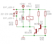
I'm trying to understand one part of my_ref schematic, led and relay section.
In attach I post the section that I'm trying to analyze.
I have a big doubt about R23. I don't understand why the value is so high and why it is 1W.
If the power is 24V and by datasheet the led has a forward voltage of 2V, on the R23 there should be less than 22V. So to have a forward current of 30mA (datasheet value) the value of R23 should be 733 ohm. Using 6,8k the current is 3mA.
What I'm missing in my calculation?
Attachments
ggerla,
Your calculations are fine. Its just that you don't need 30 mA. Higher current just cost energy and this LED is only for indicating that the speaker protection circuit is working. For example, using the datasheet of a Vishay 3 mm standard red LED (TLHR4400-AS12Z), the nominal rating for the LED is 10 mA, but at 2 mA it is producing about 1 mcd light intensity which is fine for an indicator.
If you are curious, try the LED part of the circuit with a resistor to give you 2 - 3 mA and any LED you have laying around. For example, you can use a 9V battery with 2700 or 3300 Ohm resistor and most red LEDs and see what a 2.2 or 2.7 mA LED looks like.
As for the 1W rating in the BOM, I'm guessing that is a typo. The part number listed appears to be a 1/2 W, but you are right, there isn't a need for a high power resistor.
Have fun.
Jac
Last edited:
ggerla,
Your calculations are fine. Its just that you don't need 30 mA. Higher current just cost energy and this LED is only for indicating that the speaker protection circuit is working. For example, using the datasheet of a Vishay 3 mm standard red LED (TLHR4400-AS12Z), the nominal rating for the LED is 10 mA, but at 2 mA it is producing about 1 mcd light intensity which is fine for an indicator.
If you are curious, try the LED part of the circuit with a resistor to give you 2 - 3 mA and any LED you have laying around. For example, you can use a 9V battery with 2700 or 3300 Ohm resistor and most red LEDs and see what a 2.2 or 2.7 mA LED looks like.
As for the 1W rating in the BOM, I'm guessing that is a typo. The part number listed appears to be a 1/2 W, but you are right, there isn't a need for a high power resistor.
Have fun.
Jac
thanks for the explanation. I would reuse the same circuit in my preampli. I would use the led to see that power is ok and relay to open/close the output.
The difference is that I would use 12V (not stabilized) and not 24V.
The only question is whether you need a relay on a preampli. If you are using it for a soft start, cool.
The main point of the circuit in the My_Ref is to protect the speaker in case something fails in the amplifier and generates a DC voltage. The part of the circuit that turns on the transistors so that the relay can close are needed for speaker protection.
Jac
The main point of the circuit in the My_Ref is to protect the speaker in case something fails in the amplifier and generates a DC voltage. The part of the circuit that turns on the transistors so that the relay can close are needed for speaker protection.
Jac
The only question is whether you need a relay on a preampli. If you are using it for a soft start, cool.
The main point of the circuit in the My_Ref is to protect the speaker in case something fails in the amplifier and generates a DC voltage. The part of the circuit that turns on the transistors so that the relay can close are needed for speaker protection.
Jac
The scope of the relay is for "soft stop". Sometimes it happens that shutting down everything I have a little "bump" in the speakers.
I'm still evaluating to use it or no... I would do some other tests before take a decision.
Yes, absolutely but use Evo A compensation, the updated BOM for old boards and solder R11 as in the pic (on bottom side of boards):
The latter boards (from 1.5 and Up) have tenfold less distortion and most of this reduction is due to R11 position.
Since I posted this in the wrong forum last time I’m reposting it here. I just recently built up V1.05 boards I acquired from a member. They sound wonderful but my question is should I move R11 from its original position on the board to the position Dario showed in this picture?
Thanks, Pete
Attachments
They sound wonderful but my question is should I move R11 from its original position on the board to the position Dario showed in this picture?
Hi Pete,
if you want (hopefully) tenfold less distortion, yes.
")
It's an easy and quick mod.
There has been much discussion about using "better" opamps to replace the LM318 of the original design. I have used a Sparkos discrete opamp in my active crossovers with great success. Its sound quality surpasses any other opamp I have tried, including what was once considered the "gold standard" OPA627.
If someone would please examine the data sheet of the Sparkos SS3601 regarding its suitability for application in the MyRef, I would greatly appreciate it. I am not qualified to evaluate the data, but I would be willing to undertake a trial of the opamp and report my findings here if anyone sees potential.
The first objection is that the discrete opamp is DIP8. Sparkos also sells an adapter for DIP8 to SOIC8, which is a pretty nifty device on its own.
Peace,
Tom E
Tom,
The swap most likely will require feedback loop changes. To maximize Sonics and maintain stability.
I think most are running simulations to get a starting point and then fine tune with measurements. It can be very labor intensive.
One I like is OPA1612. Being a dual it is not drop in here.
The swap most likely will require feedback loop changes. To maximize Sonics and maintain stability.
I think most are running simulations to get a starting point and then fine tune with measurements. It can be very labor intensive.
One I like is OPA1612. Being a dual it is not drop in here.
There has been much discussion about using "better" opamps to replace the LM318 of the original design. I have used a Sparkos discrete opamp in my active crossovers with great success. Its sound quality surpasses any other opamp I have tried, including what was once considered the "gold standard" OPA627.
The first objection is that the discrete opamp is DIP8. Sparkos also sells an adapter for DIP8 to SOIC8, which is a pretty nifty device on its own.
Peace,
Tom E
Tom: two things..
Logicalsys.com also has a similar product to Sparkos...search for PA-DSO-0803-D250-08/2 (an SOIC emulator adapter).
I’ve tried a number of alternative op-amps on Dario’s Evo A boards which have included OPA627, OPA827, and ADA4627. One I’ve yet to try is OPA828. OPA1641 has also been attempted. All these have been previously tried by more experienced builders first: mostly George (Joseph K). I followed instructions for using them from numerous posts by George and others in this thread. All except LM318 have required either a 3.3 or 5 pF silver mica cap mounted across pins 2&6 to prevent possible oscillations. I have no oscilloscope to check for oscillations so I just used the silver mica caps as per recommendation. A few SMD parts either have to be removed or values changed and C9 can generally be eliminated. Post #3085 is a good place to start.
I liked OPA627 the least on my system and really liked ADA4627. All my op-amp changes have been SOIC changes. I’ve never used the adapters on Dario’s boards. I have used them when rolling on-amps on Class D amps but those are all dual op-amps and there haven’t been any grave warnings of oscillations in the Class D amp forums when rolling them. Doesn’t mean one is Scott-free however.
Hope that gave you some information to go forward with.
Cheers,
Pete
Thank you both for your responses.
I have contacted Andrew at Sparkos, and he believes it would be worthwhile to try. Of course, he's interested in selling his product, but he understands the goal here is better sound. He offers a guarantee, so if the device is not harmed he would accept it back at no charge if a trial proves unsuccessful. He has also offered an unspecified quantity discount. Right now, he is offering a 20% discount on anything purchased.
Since the SS3601 opamp requires decoupling plus and minus power supplies to ground, I wonder if C7 could be left open and instead use a cap between those holes and the ground legs of each regulator, a very short path. Perhaps that would be a better decoupling even without the introduction of new opamps? There is much controversy over which decoupling method is more effective: a single cap between + and - or each decoupled separately to ground. Easy to implement a trial. Has anyone done it already?
Peace,
Tom E
Tom,
I have tried different decoupling schemes many years ago, when doing the series of measurements.
I remember I did not find better (I mean, technically, looking for oscillations and instability) the alternative methods (that is, really those are the classic methods, and the one in the FE is 'alternative')
So there was no extra premium coming with more classic style decoupling.
I did not experiment too much by listening. My thinking was that loads of experiments and discussions had been performed sound-wise, before..
But recently I had sat down (effect of lockdown) to measure the usual parameters of the applied FE shunt PS.
And now I am thinking to maybe try some other methods as well, - I have mentioned it already to Dario.
Should only harvest some extra free time amongst other projects real life & hobby..
Re the discrete opamps: I do understand the reasoning behind. I am a long time user of Sonny's Mirand dac, which sports his beautiful prof. style / standard discrete stages (I do think they are more thoroughly made than the Sparko's)
Problem with these stages is the usually quite unique, multiple pole compensation scheme, which renders their application in a composite amp loop - nightmare-ish.
Plus, naturally, no simulation model exist, so they can not be pre-tuned before implementation, so nasty sorprises, oscillations etc are to be expected, some overheating and other nasties to be undertaken..
So it's a fight.
So much so, that for escaping the gates of hell but still having my cake - I did order Sonny's A1. 2 amplifier modul, which is advertised by himself as a 'composit' topology, applying his (my favorite) discrete opamp modules as input stage..
I have them. They sound real good. Obviously tweaking could start even on these.
But but.. My full fledged EVO with OPA828, texas metal foils, double current pump etc..
Is still there, sitting on it's throne.
FS: Mirand A1 V1.2
Ciao! George
Last edited:
Tom,
Very interesting idea. Although the alternate opamps suggested by George sound different than the LM318 in on an FE board and I would even say a positive tradeoff in sound quality, the biggest thing for me is the chance to remove C9. That is only possible with, for example, the OPA827, because the very low input bias current. The Sparkos website doesn't list those kind of parameters, so its hard to know if the Sparkos would help with C9, in addition to the compensation issues mentioned by others.
I'm sure if you asked the Sparkos guy, he would send along the full datasheet and you could forward that to George. After all, it looks like George doesn't have enough to do. ;-)
Although that I know some don't agree, I find that opamps have different character in different circuits. For example, the OPA827 that sound quite good in the FE sounds pretty unbalanced in a dac I recently built. I don't know what that means here other than there seem to be a lot of possible problems using it in the FE circuit.
Last edited:
Thanks, Jack. Actually, the Sparkos data sheet is contrary to many other discrete opamps in that he provides thorough, meaningful data. It does include the input bias current spec: 4.5 uA typ, 6 uA max. I don't know where that falls on the scale of acceptable levels to allow removal of C9, but I think it's lower than the OPA827.
Yes, George, perhaps the two-pole compensation would prove problematic in a MyRef implementation, although Andrew at Sparkos did not mention it in his reply to my inquiry. He does claim that it is "extremely tolerant of capacitive loading and high feedback network resistance" if that means anything here.
Do either of you see a problem with local decoupling to the ground legs of the regulators instead of using C7 across + and -? It would be convenient.
I would not be asking about this at all if there was a clear consensus about which alternative monolithic opamp was the best replacement for LM318. There doesn't seem to be a winner that pleases everyone, which makes me wonder if it's really worth the bother. On the other hand, I KNOW the SS3601 is a device which provides excellent sonics in other circuits which are not as complex as the MyRef.
Peace,
Tom E
- Home
- Amplifiers
- Chip Amps
- My_Ref Fremen Edition - Build thread and tutorial