Almost finished upgrading my MyRef modules to the last Mouser BOM with few exceptions:
-installed Hexfreds rectifying diodes
-Mundorf Mlytic filtering caps
- Amtrans caps/polystyrene c7
- Susumu RS audio for 3k3, 22k, 47k resistors.
-lowered R101,201 to 39 ohm in order to increase a little the current in LM318 (now the LM317,337 work a bit hot)
-repositioned R11 as indicated by Dario some time a go
-Evo mod applied (R3 still 0R47 for another few days, as i want to manufacture some serie-paralel resistor like Jac did)
- kept old BC639/640 (i'm not sure if the pcb holes are large enough for installing the much powerful BD139/140). Maybe Dario can say if it works. I think i have pcb rev 1.0
New custom made toroidal 350VA 4x25V, schielded
The change in sound is WOW. I never knew my poor Subbu DAC can deliver such nice trebles. Great soundstage, airy sound, great bass but a bit too much for the moment, waiting to settle everything. A lot of details came into light. Really surprised.
Next and last test will be to change LM318 to OPA 827 to see how i like the sound.
I will let you know how it worked.
Thanks again Dario and Mauro (RIP) for making this project to exist.
Thank you Atupi, yes, I like very much silver mica sound, too, especially in feedback nets, the question is that also in the original BOM C34 is silver mica, but in SMD.
I only have through-hole version and there is no problem to solder it on board, but maybe it's not the same thing about parasitic current due to leads and longer signal path... who knows?
I only have through-hole version and there is no problem to solder it on board, but maybe it's not the same thing about parasitic current due to leads and longer signal path... who knows?
Today I did the big step in changing the opamp and installed OPA827, a 100pf PPS smd Panasonic cap 667-ECH-U1H101JX5 in C32 and a 5pf silver-mica CDE cap between pins 2&6 of opamp. Also shorted C9.
R3 is still Caddock 0.47ohm until i receive the next postal delivery to change it.
I don't know if i should continue experimenting with some other caps for C32. I have some fkp2 100pf already and maybe to try to source some polystyrene ones?
Changes are quite impressive: first impression was like stereo scene is more wide and large, almost holographic (like someone pushed the surround button like the 90's boomboxes had), sound is more liquid and voices are more present and well defined.
Sound is also more euphonic and I'm tempted to listen louder and I'm surprised how my speakers can go in both extremes of audio spectrum, lower bass is more present and I can hear a lot of details in trebles.
I'm still trying to figure it out if the sound is not too precise, too audiophile.
I have observed the input sensitivity is a bit lower compared to Lm318. Dc measured on output is close to zero as my poor DMM shows.
I think i need a better DAC now")
I remember i read somewhere on this long thread that Myref with a jfet opamp has a bigger input impedance and I don't need many buffers or complicated preamps?
What can i say more, impressive amp.
R3 is still Caddock 0.47ohm until i receive the next postal delivery to change it.
I don't know if i should continue experimenting with some other caps for C32. I have some fkp2 100pf already and maybe to try to source some polystyrene ones?
Changes are quite impressive: first impression was like stereo scene is more wide and large, almost holographic (like someone pushed the surround button like the 90's boomboxes had), sound is more liquid and voices are more present and well defined.
Sound is also more euphonic and I'm tempted to listen louder and I'm surprised how my speakers can go in both extremes of audio spectrum, lower bass is more present and I can hear a lot of details in trebles.
I'm still trying to figure it out if the sound is not too precise, too audiophile.
I have observed the input sensitivity is a bit lower compared to Lm318. Dc measured on output is close to zero as my poor DMM shows.
I think i need a better DAC now
I remember i read somewhere on this long thread that Myref with a jfet opamp has a bigger input impedance and I don't need many buffers or complicated preamps?
What can i say more, impressive amp.
Last edited:
Congrats, you seem to be a 'smooth operator', good skills.. getting the proper low output bias (yes, a few mV max) is not always that straightforward.
Your description fits my sensations nicely.
Hope it will hold on in time..
I don't think FKP2 would get better in the feedback comp. PPS is more transparent, open, vivid. A good styroflex maybe yes..
And yes, with these opamps it can be used with a potentiometer directly on the input.
And no, the input impedance is always the same, 100kohm. But you can choose an even higher value, 200k is still comfortable.
The reason is that the input CMRR is better now than with the original. Also the input common mode distortion with higher source impedances is much less - OPA827 is one of the best, least sensitive. (Also OPA627, OPA1642, OPA828 are in the top)
Also, and it could have been the principal reason for Mauro, the input impedances got more balanced with a low out Z pre in front.
(Don't forget, the other (+) input looks into ~390ohm. So a similar, few hundred ohm on the input side (dynamic, AC source imp.) resulted in a better balance for the lm318. )
The jfet input 827 is much less sensitive, for the above reasons.
So you can feed it with a pot, which can result even 12 kohm output source impedance (50kohm pot half course).
In fact, I used for a long time with nothing else just a Noble 50kohm pot in input. Nowadays I use direct connection, dac - finals. And use the HQP softwer volume control..
Ciao, George
getting the proper low output bias (yes, a few mV max) is not always that straightforward.Your description fits my sensations nicely.
Hope it will hold on in time..
I don't think FKP2 would get better in the feedback comp. PPS is more transparent, open, vivid. A good styroflex maybe yes..
And yes, with these opamps it can be used with a potentiometer directly on the input.
And no, the input impedance is always the same, 100kohm. But you can choose an even higher value, 200k is still comfortable.
The reason is that the input CMRR is better now than with the original. Also the input common mode distortion with higher source impedances is much less - OPA827 is one of the best, least sensitive. (Also OPA627, OPA1642, OPA828 are in the top)
Also, and it could have been the principal reason for Mauro, the input impedances got more balanced with a low out Z pre in front.
(Don't forget, the other (+) input looks into ~390ohm. So a similar, few hundred ohm on the input side (dynamic, AC source imp.) resulted in a better balance for the lm318. )
The jfet input 827 is much less sensitive, for the above reasons.
So you can feed it with a pot, which can result even 12 kohm output source impedance (50kohm pot half course).
In fact, I used for a long time with nothing else just a Noble 50kohm pot in input. Nowadays I use direct connection, dac - finals. And use the HQP softwer volume control..
Ciao, George
Last edited:
Thanks George and Tonix!
In my opinion the biggest change in sound character was when i changed fom old BOm to the latest one. I really don't know what part of new BOm brought this sound character change, the Hexfreds, the new resistors? (almost all smd are RS audio, the increase in current on opamp power supply, or maybe all of them)
In my opinion the biggest change in sound character was when i changed fom old BOm to the latest one. I really don't know what part of new BOm brought this sound character change, the Hexfreds, the new resistors? (almost all smd are RS audio, the increase in current on opamp power supply, or maybe all of them)
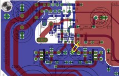
C9 position on Rev 1.0 board
Hello, sorry for the dumb question, where I have to place the 220 uF C9 capacitor on my 1.0 board? it seems in parallel with another one, and another little "resistor-like" seems to be populated, but without any kind of value. One terminal is in common with the + C9 terminal...
Hello, sorry for the dumb question, where I have to place the 220 uF C9 capacitor on my 1.0 board? it seems in parallel with another one, and another little "resistor-like" seems to be populated, but without any kind of value. One terminal is in common with the + C9 terminal...
Attachments
![P00413-130511[1].jpg](/community/data/attachments/766/766488-2f539b1c9d1cf92739cf2156897447b6.jpg)
Interesting. It should have been marked. What you are looking at is R10, 390R, and you most definitely need it. It is a key part of the gain setting feedback circuit. You said that one terminal is common with +C9. The other terminal should be common with R7. If not, check if its in common with R11 and post again please.
Jac
Edit
I think I see your 390R running next to your big input cap, C13. Was that one marked R10? I can't see it clearly in the photo. In this early version, we were experimenting with the order of C9 and R10, which are in series. The original version had C9 first, then R10. In that case, C9 would go into the holes just above the "resistor like" component and the higher set of 3 holes would be left empty. In this version, R10 would be in the position that you appear to have it mounted.
The alternate order for C9 and R10 became preferred and later boards don't have the option. If you can, it would be slightly better to remove R10 from its current place and place it in the holes of the "resistor like" component. Then put C9 in the group of 3 holes near the top of the picture. The result should be R10 with its left terminal common with R7 and its right terminal common with the + terminal of C9 (in the upper position). The lower position of C9 would be not used. The right or negative C9 terminal would be connected to the ground plane.
I hope I was able to explain this clear enough. Its hard to describe. Please ask questions if its not clear.
Of course, there are no dumb questions. This one in particular was tricky unless you were around back then. I'm feeling a little bit old.
Last edited:
Hello Jac, no the resistor R10 is already mounted, is the one just near to the C1 capacitor. Having a look at the schematcs it seems like a "capacitor first, resistor second" vs. "resistor first/capacitor second" choice, with the first one that terminates on R 11 1 Ohm resistor before Gnd and the second one directly to Gnd.
Probably I have to populated the marked C9 capacitor place, I've just tested the electrical continuity and it should be correct. Anyone used the Rev 1.0 board, just to have a confirmation about the correctness?
Massimo
Probably I have to populated the marked C9 capacitor place, I've just tested the electrical continuity and it should be correct. Anyone used the Rev 1.0 board, just to have a confirmation about the correctness?
Massimo
Jac, but in this case the feedback net terminated directly to ground, not to the 1 Ohm resistor (R 11). By this way the input net and the feedback net won't see the same potential. Is that correct? In all the Dario schematics the feedback net terminates on R 11, not directly to ground (I admit, I'm a little bit confused about it).
Probably I'll go populating the C9 indicated place, it's quite a pity, the unmarked place should have been perfect to try some bypass small capacitor in parallel with the big electrolytic one...
Probably I'll go populating the C9 indicated place, it's quite a pity, the unmarked place should have been perfect to try some bypass small capacitor in parallel with the big electrolytic one...
- Home
- Amplifiers
- Chip Amps
- My_Ref Fremen Edition - Build thread and tutorial