Sorry, but I probably should clarify something. As I understand it, the orientation of a polarized cap is only important if the AC signal is riding on a non zero volt bias. This would not be the case for the input signal. If there is a positive bias, you must connect the positive side of the cap to it. Or poof!
Many amps run on a single voltage power supply. The output voltage (from the amp to the speakers), is riding on a DC bias equal to 1/2 the supply voltage, meaning it's always positive. In this case, the positive side of the cap must be connected to the amp side, since the input voltage is swinging, at max, from 0 to the supply voltage. For a single-ended output, the output voltage is now riding on a 0 volt bias.
Mike
Tantalum capacitors
Hi Mike,
I see. My method trying to determine which was "negative" or "positive" was flawed! Thank you for the explanation.
As for your question in the last paragraph, all I am doing is substituting a higher value part. I think the original caps were tantalum (220nF) and I am just replacing them with tantalum caps with a value of 1uF.
Are tantalums the same as electrolytics? I know on those you must mind the polarity. And I was surprised to learn from Google that the tiny tantalum caps had a + and a - lead as well. Just wanted to install them correctly. (Since on these Chinese boards you are never certain if the original stuff is marked correctly and/or installed correctly to begin with.)
Thanks,
Mark
Just wanted you to understand that the inputs to the caps are not ground. If you were to pull out the potentiometer holes 2 and 3 would be floating.
Technically, you could connect a preamp directly to holes 2 and 3 and be just fine.
Although they will work (not sure if the orientation matters for an AC signal), I'm curious why you are going with an electrolytic cap in the first place?
Mike
Hi Mike,
I see. My method trying to determine which was "negative" or "positive" was flawed! Thank you for the explanation.
As for your question in the last paragraph, all I am doing is substituting a higher value part. I think the original caps were tantalum (220nF) and I am just replacing them with tantalum caps with a value of 1uF.
Are tantalums the same as electrolytics? I know on those you must mind the polarity. And I was surprised to learn from Google that the tiny tantalum caps had a + and a - lead as well. Just wanted to install them correctly. (Since on these Chinese boards you are never certain if the original stuff is marked correctly and/or installed correctly to begin with.)
Thanks,
Mark
Mike,
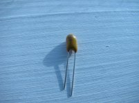
OK, here are some photos. The capacitor: it is hard to see the writing but the + as I understand it is on the longer lead.
RE: cap in holes 3 and 4:
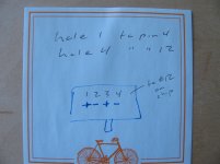
The drawing indicates how I designated the holes, etc. And the + or - are showing how the two caps on the "master board" are oriented. In other words, the writing on both those original capacitors faces the chip.
I traced from pin 12 of the chip to hole #4 and the way the cap is oriented on the master board would make the negative lead of the cap - not the positive as you indicate - facing the chip.
I don't understand. Did they orient the capacitor wrong?
RE: cap in holes 1 and 2:
The cap for holes 1 and 2 seems to be correct. The writing faces the chip. In other words, the + lead on the cap at hole #1 orients towards/connects to pin #4 of the chip. (This all is as you said it should be.)
Mark
OK, here are some photos. The capacitor: it is hard to see the writing but the + as I understand it is on the longer lead.
RE: cap in holes 3 and 4:
The drawing indicates how I designated the holes, etc. And the + or - are showing how the two caps on the "master board" are oriented. In other words, the writing on both those original capacitors faces the chip.
I traced from pin 12 of the chip to hole #4 and the way the cap is oriented on the master board would make the negative lead of the cap - not the positive as you indicate - facing the chip.
I don't understand. Did they orient the capacitor wrong?
RE: cap in holes 1 and 2:
The cap for holes 1 and 2 seems to be correct. The writing faces the chip. In other words, the + lead on the cap at hole #1 orients towards/connects to pin #4 of the chip. (This all is as you said it should be.)
Mark
Attachments
I assume the cap in the picture is the 1uf electrolytic? The caps installed on the board on not electrolytic, and therefore orientation is not important. I usually install then such that I can still read them, but that's my OCD.
For some reason I thought you were installing 10uf caps. I may have some 1uf Wima film caps I can mail you. I can check if you want.
I'm going to do some math using the 1uf value. Electrolytic caps can tolerate a very small reverse voltage for a short period of time.
Mike
For some reason I thought you were installing 10uf caps. I may have some 1uf Wima film caps I can mail you. I can check if you want.
I'm going to do some math using the 1uf value. Electrolytic caps can tolerate a very small reverse voltage for a short period of time.
Mike
Mike,
Read my other posts carefully.
Tantalum.
Is this the same thing as electrolytic?
Again, what do you make of the fact that on the master board the negative lead of the second cap (holes 3 and 4) orients towards the chip pin 12. Not, the positive lead.
Do they have the master board populated wrong? Because all writing faces the chip. Which would make it
+ - + -
1 2 3 4
Mark
Sorry...don't seem to be helping much. Here are my assumptions...
The caps that came with the board (labeled 224) are .22 uf non-polarized. Probably ceramic. The writing is probably arbitrary, as there is no + or - orientation. It can be mounted any way.
A tantalum capacitor is a type of electrolytic capacitor. Since the picture of your 1uf cap has "polar" markings, it must be polarized. You want to use it with an AC signal, which should be fine as long as the voltage across it is small relative to the caps maximum voltage.
You are going from a .22uf cap to a 1uf cap to reduce the -3db voltage point by 4 octaves.
Not sure what I'm missing in your previous posts.
Mike
Hi Mike,
Yes, yes, I did some reading and now understand that tantalum caps are indeed a type of electrolytic cap. Thanks for your patience and steering me in the right direction. Yes, you definitely are giving me a good education and I thank you for it. I don't know much. And, if it were not for guys like you, would know lots less.
Oh, I see. You say the original caps are ceramic and therefore non-polarized. Oh, I thought they were tantalums too.
Well, I don't know where I got the idea to use these tantalums. I know I read somewhere to try a 1uF value and probably somewhere else that tantalums "sound good". So, a rookie choice of parts I guess.
Mike, in your opinion, should I replace these caps with ceramic ones? And is the 1uF value OK? Or should I just put the original ones back in? Any suggestions?
Incidentally, I'd be thrilled to try the Wima caps if you find them. And happy to reimburse you for the cost and postage of course. Private Message me if you come up with those.
Regards,
Mark
Last edited:
Hi Mike,
Yes, yes, I did some reading and now understand that tantalum caps are indeed a type of electrolytic cap. Thanks for your patience and steering me in the right direction. Yes, you definitely are giving me a good education and I thank you for it. I don't know much. And, if it were not for guys like you, would know lots less.
Oh, I see. You say the original caps are ceramic and therefore non-polarized. Oh, I thought they were tantalums too.
Well, I don't know where I got the idea to use these tantalums. I know I read somewhere to try a 1uF value and probably somewhere else that tantalums "sound good". So, a rookie choice of parts I guess.
Mike, in your opinion, should I replace these caps with ceramic ones? And is the 1uF value OK? Or should I just put the original ones back in? Any suggestions?
Incidentally, I'd be thrilled to try the Wima caps if you find them. And happy to reimburse you for the cost and postage of course. Private Message me if you come up with those.
Regards,
Mark
Hey Mark
Don't know if tantalums are any good or not. Here's a link to some info about electrolytics in general and tantalums in some detail...
Capacitor Characteristics
I found some 1uf Wimas. I need to desolder them from a test board, but they should be good. PM me your address, and I'll mail you a few. No need to reimburse for the price of a stamp
With the original .22uf cap, your -3 db point will be around 24 hz.
A 1uf will be fine. Your -3 db point will be around 5 hz. At 20 hz, it will be down .3 db. Would be amazing if your speakers were that good!
Mike
Last edited:
Thank you
Thank you Zek,
I am getting an education on this from M. Boxler too. Rookie mistakes!
I guess a film type is best? A Wima as you and Mike have mentioned or even another type.
Mark
@Mark2727
Do not put electrolytic or tantalum capacitors on the signal path. It is best to use block capacitors (such as Wima).
Thank you Zek,
I am getting an education on this from M. Boxler too. Rookie mistakes!
I guess a film type is best? A Wima as you and Mike have mentioned or even another type.
Mark
Last edited:
Sweet!
Ah.....K-Horns! I shouldn't have sold my La Scalas, but I have way too small a room for them. (10.5 foot by 11 foot.)
So, the one amp runs the woofers? And the other does the "squawker" as Klipsch calls the tweeters and mid-range?
Very nice!
Mark
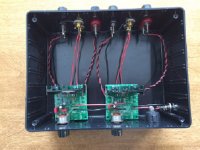
Have two of them in a Radio Shack project box. Bi-amping my Klipsch K-horns. Crazy good!
Ah.....K-Horns! I shouldn't have sold my La Scalas, but I have way too small a room for them. (10.5 foot by 11 foot.)
So, the one amp runs the woofers? And the other does the "squawker" as Klipsch calls the tweeters and mid-range?
Very nice!
Mark
Ah.....K-Horns! I shouldn't have sold my La Scalas, but I have way too small a room for them. (10.5 foot by 11 foot.)
So, the one amp runs the woofers? And the other does the "squawker" as Klipsch calls the tweeters and mid-range?
Very nice!
Mark
One to the woofers, the other to two-way passive crossovers to split the signals between the squawkers and tweeters. My room isn't big enough either, but they sure sound great!
Does anyone have a suggestion for a "better" capacitor where that original 10uF one is on the board? It's the far left cap.
Is that one in the signal path?
I put a higher value (50uF) one there. It, like the original, is an electrolytic. I'm wondering if a higher quality one would net me anything.
Mark
Is that one in the signal path?
I put a higher value (50uF) one there. It, like the original, is an electrolytic. I'm wondering if a higher quality one would net me anything.
Mark
Does anyone have a suggestion for a "better" capacitor where that original 10uF one is on the board? It's the far left cap.
Is that one in the signal path?
I put a higher value (50uF) one there. It, like the original, is an electrolytic. I'm wondering if a higher quality one would net me anything.
Mark
Hey Mark
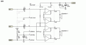
As I understand it, the purpose of that cap (and the two 47k resistors) is to prevent turn on pops. When the amp is powered on, it delays the voltage to the standby and mute pins long enough for the power supply cap to charge.
A larger value will only help if you were getting turn on pops with the 10 uf.
I don't think it affects turn off pops (I get those, albeit not really loud), but it would be interesting if you noticed a difference with the 50 uf.
They are not in the signal path.
Mike
I thought there was something odd about that board. Usually there are three resistors. Two for the mute/standby circuit to help with the pops. The third is the current limiting resistor for the led. Hard to tell, but they may be sharing one of the two "pop" resistors for the led resistor. Are they both 47K? They should be positioned in the attached schematic.
The 104 capacitor should be parallel to the power capacitor, and I believe it's there to remove high frequency noise from the power supply. I've heard it said that, with a clean PS, it can be removed.
Mike
The 104 capacitor should be parallel to the power capacitor, and I believe it's there to remove high frequency noise from the power supply. I've heard it said that, with a clean PS, it can be removed.
Mike
Attachments
Does anyone have a suggestion for a "better" capacitor where that original 10uF one is on the board? It's the far left cap.
Is that one in the signal path?
I put a higher value (50uF) one there. It, like the original, is an electrolytic. I'm wondering if a higher quality one would net me anything.
Mark
100uf not bipolar is a better option for less turn on noise. Quality is pointless.
Get tantalums around the wrong way and they make nice fire crackers.
I had a batch from a well-known Japanese capacitor manufacturer that were marked (and sold) with the wrong Voltage rating. My circuit required 35V working capacitors, since the supply was 24V and I like a bit of a margin. These were supposed to be 35V......
I tried six of the batch with the same explosive results before I sent the entire 1000 piece batch back to the suppliers, including a photo of the burn I sustained as the first one exploded!
Thanks
Thank you, fellows, for the explanation about the 10uF cap. Yes, once I saw the schematic MBoxler posted I see it's part of the mute circuit.
Not much turn-on/turn-off noise on this amp to begin with so I guess the 50uF I put in will suffice.
Interesting stuff.
And, no need to mess with the tiny ceramic (104) capacitor either. No background noise on this amp. I will leave it as is.
I guess once I replace the tantalums I shouldn't have installed with some "box type" Wimas or similar (originals marked as "224") I've taken this one as far as is reasonable to go. I already replaced the original filter capacitor with a low ESR one having a higher voltage rating.
You guys are a great help. Thank you!
Mark
- Home
- Amplifiers
- Chip Amps
- What the heck? It's less than lunch!