Hey I missed your suggestion about the diodes in series. Can you explain how to install them, maybe link to a schematic? Thanks.I am not convinced that China items will do significantly worse than non-China items. After all, where are the wafer houses, used by well known brand owners, located? This is no high tech item.
Anyway, why not give it two ordinary 5A diodes in series and a 2200uF for decoupling when using 19V?
If my PSU is 19V 3.42A, how many uF do I need? I read something like 2200uF per ampere, minimum. What do you guys use? I know Destroyer OS suggested multiple 1000-1500uF for lowest ESR. I paralleled 6x1000uF after the IRF540 but this time I'd like to try without the MOSFET multiplier.Use a simple rectifier diode and a cap (D-C). A diode will drop the 19V a bit (up to 1V under load), and a big cap will add cohones and better peceived "detail"; whatever this means to you. (I use this approach myself).
I would also say that using a couple low-ESR caps in parallel works better than one large one. My suggestion is 2x 10.000uf + 1x 4700uF, all rated 25V.
But first you must be sure that your laptop PSU handles all this capacitance without hiccups at power-up! IF IT DOES NOT; your best option is imho using a "slow starting" capacitance multiplier, but with a darlington transistor - NOT a mosfet. Try a BDX53.
Last edited:
Trivial drop of voltage across one or more series coupled diodes:
Diodes To Drop Voltage | Electronics Forum (Circuits, Projects and Microcontrollers) (first posting),
You only need two diodes in series to be below the specified 18V.
On the output you put a good electrolytic capacitor. Minimum of 2200uF but preferably 4700uF-10000uF. The size depends on how much capacitance you have on the input of the diodes to "re-fill" the capacitor at the output of the diodes.

Trivial drop of voltage across one or more series coupled diodes:
Diodes To Drop Voltage | Electronics Forum (Circuits, Projects and Microcontrollers) (first posting),
You only need two diodes in series to be below the specified 18V.
On the output you put a good electrolytic capacitor. Minimum of 2200uF but preferably 4700uF-10000uF. The size depends on how much capacitance you have on the input of the diodes to "re-fill" the capacitor at the output of the diodes.
Thank you my friend. If my SMPS is 3.42A, is it safe to use 2xMUR460 in series with the positive voltage?
Hi Jonathan,
The MUR460 is a 4A diode. Your TDA7297 current consumption will be dynamic (less that the max. current in average). The MUR460 should be fine if you mount them above the PCB with long leads (like in vintage Japanese amplifiers) such that they are better cooled.
The MUR460 is a 4A diode. Your TDA7297 current consumption will be dynamic (less that the max. current in average). The MUR460 should be fine if you mount them above the PCB with long leads (like in vintage Japanese amplifiers) such that they are better cooled.
Looking to setup one of these TDA7297 amps for use above 120hz. Doing the calcs I come up with .044uF input caps. Am I missing anything?
Based on 30k input impedance, looks right to me.
hi again chaps. these are now avaiable pre assembled and i have just bought a version which is housed in a nice plastic enclosure from douksound on ebay for £10.99.
can you help me with the speaker connections as the + and - are reversed on the left and right channel.
do you think this is a mis print on the board or does it seem right ?
thanks
phil

ok the image has not really worked. if you have a moment please see this link.
in the above image looking from the top. the left channel has minus for the left connection and plus for the right. the right channel has plus for the left speaker terminal and minus for the right. on other boards i have seen including one that i have this is not the case. hope thats clear
TDA7297 Digital Power Amplifier HiFi Stereo Audio Amp Board + Case + Cooling Fan 6434081810427 | eBay
can you help me with the speaker connections as the + and - are reversed on the left and right channel.
do you think this is a mis print on the board or does it seem right ?
thanks
phil
ok the image has not really worked. if you have a moment please see this link.
in the above image looking from the top. the left channel has minus for the left connection and plus for the right. the right channel has plus for the left speaker terminal and minus for the right. on other boards i have seen including one that i have this is not the case. hope thats clear
TDA7297 Digital Power Amplifier HiFi Stereo Audio Amp Board + Case + Cooling Fan 6434081810427 | eBay
Tantalum capacitors
I have a question. I've read tantalum capacitors have a direction/polarity.
I have this board in use right now and I replaced the two tiny capacitors labelled "224" with larger value tantalum caps.
Here is the board:
AC/DC 12V TDA7297 2x15W Digital Audio Amplifier DIY Kit Dual-Channel Module JKHW 834093921900 | eBay
I question if I installed them correctly. Can someone straighten me out?
Let's assume you are looking at the top of the unit, with the volume pot in from of you. And the larger, 10uF capacitor is on your left. And then, let's assign a number to each of the 4 holes the tantalum caps would go in from Left to Right. Or, in other words, there's that larger capacitor (the 10uF one), then holes for the tantalums are 1,2,3,4.
I order to determine which of the holes were "negative", I used a multi-meter set to beep when I have continuity between a known ground (the ground of the input part of the board) and then I put the other lead of the meter on each of the four holes: 1, 2, 3, 4.
I determined 2 and 3 were making a beep with the ground of the input. Therefore, the negative leads of the capacitors would be inserted into 2 and 3. And, I put the new tantalum capacitors in with the negative leads inserted into holes 2 and 3.
YET, when I looked at my untouched, unmucked with master tda7297 both of the caps were facing the back side towards the chip. If I am not getting confused, this would make holes 3 and 1 the negatives. (And, not the way I have installed my new capacitors).
Could someone help?
I hope this isn't too confusing.
Just tell me:
1) Are tantalum capacitors really polarity dependent?
2) Given my numbering system where hole #1 is (top side view) closest to the 10uF cap, and #4 is the farthest away... tell me the what if the positive or negative lead goes into each hole.
For example:
#1, 2, 3, 4
+, -, -, +
Some explanation like that would be great.
Thanks,
Mark
Hey Mark
Do the capacitors have any + - markings?
From the Ebay picture of the bottom for the board, The two middle holes are connected to the volume control, not ground. Weird.
If they are polarized, most applications I've seen have the + side of the capacitor facing the chip. In your case that would be holes 1 and 4.
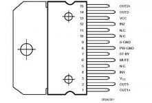
Hole 1 should connect to pin 4 of the chip.
Hole 4 should connect to pin 12 of the chip.
These are the chips inputs.
Mike
Hello Mike:
Yes, tantalums (as I learned after I installed them!) are marked with a +. And the longer lead is the +.
And, yes, the holes I designate at 2 and 3 do go to the middle portion of the volume pot.
I got continuity from 2 and 3 to the ground of the input. That is why I thought those were the negative "holes".
Mark
I see on my unmucked with, "master" board that the writing on their caps faces the chip. Assuming the caps were put in correctly on this master board and, according to my numbering system (when viewing from the top of the board) where hole 1 is leftmost, or nearest the 10uF capacitor, and hole #4 is rightmost, or nearest the large filter capacitor that would make the holes:
#1 +
#2 -
#3 +
#4 -
I did not catch that my capacitors were marked with a +. And I wrongly assumed the longer lead was the - lead. When actually it is the + lead. Also, as mentioned before I thought that holes 2 and 3 were -. (Whether they actually are I still don't know.)
So, in fact, I actually installed mine this way:
#1 -
#2 + (originally thinking this lead was a negative lead)
#3 + (originally thinking this lead was a negative lead)
#4 -
So, I am guessing if I re-orient my first cap in holes 1 and 2 it will be correct?
Mark
No firecrackers so far
Not so far, and I don't know if I have these oriented correctly or not.
I've oriented electrolytics the wrong way, and yes...firecrackers! Quite quickly too.
Mark
Get tantalums around the wrong way and they make nice fire crackers.
Not so far, and I don't know if I have these oriented correctly or not.
I've oriented electrolytics the wrong way, and yes...firecrackers! Quite quickly too.
Mark
I got continuity from 2 and 3 to the ground of the input.Mark
Hey Mark...
Perhaps the term continuity is a little misleading.
If the volume control is turned fully counter-clockwise, there will be around 0 ohms between the input to the caps (holes 2 and 3) and ground. All the signal goes to ground (quiet).
If the volume control is turned fully clockwise, there will be 50K ohms from the input to the caps and ground. All the signal through the caps and into the amp (loud).
There is always continuity, but not always 0 ohms.
Mike
Hi Mike,
So, you are telling me my test for continuity was not valid for determining which of the holes was "negative"? I was trying to determine where to place the negative lead of the tantalum capacitors.
What would have been a better way to determine how to orient those capacitors?
I guess what you are telling me is I need to look at the chip pin out and determine it from there. I will check that but it may not mean all that much to me I have to admit.
Obviously, I'm not too good at tracing circuits.
Thanks for your continuing help.
Mark
Just wanted you to understand that the inputs to the caps are not ground . If you were to pull out the potentiometer holes 2 and 3 would be floating.
Technically, you could connect a preamp directly to holes 2 and 3 and be just fine.
Although they will work (not sure if the orientation matters for an AC signal), I'm curious why you are going with an electrolytic cap in the first place?
Mike
. If you were to pull out the potentiometer holes 2 and 3 would be floating. Technically, you could connect a preamp directly to holes 2 and 3 and be just fine.
Although they will work (not sure if the orientation matters for an AC signal), I'm curious why you are going with an electrolytic cap in the first place?
Mike
- Home
- Amplifiers
- Chip Amps
- What the heck? It's less than lunch!