Firstly you don't want to use normal opamps unless you are willing to accept the maximum voltage limitation.
Secondly there are well-proven, cleverer ways to parallel opamps.
Check out the datasheet of OPA551, Fig. 9 (and 10).
And yes, we have done this before.
Patrick
Figure 9 illustrates a master/slave circuit, not a parallel circuit. Both op amps share the current load; but it is not true parallel. The second amp is a "slave" to the first amp. This avoids circulating currents entirely. It is indeed clever, although not unusual.
By the way, that op amp looks like it could be useful. I wonder how its audio performance is?
Vos still causes a current in the sharing R - the "slave" also must have input CM range up to the "master" output Vswing - not always the case with otherwise good op amps
plus "circulating current" isn't all bad - you can deliberately add Vos - to bias the outputs into Class A push-pull:
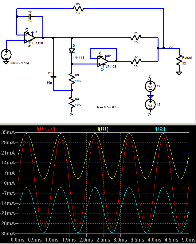
there is a small stability hit too - the slave's phase shift adds a complex load to the master output - could be a probelm if very different GBW op amps are used together
plus "circulating current" isn't all bad - you can deliberately add Vos - to bias the outputs into Class A push-pull:
there is a small stability hit too - the slave's phase shift adds a complex load to the master output - could be a probelm if very different GBW op amps are used together
Last edited:
it seems worth using better suited op amps
the TPA6120 are 100 MHz CFA - certainly need high frequency layout, 200 MHz 'scope highly recommended
but they are designed to put out 400 mA, swing to ~1.2 V of their +/-15 V rails
as dual op amps the paralleled output could be 800 mA - heatsinking is the next issue
they have the leadframe the die is attached to exposed on the undersurface where is is intended to be soldered to a PBC pwr plane for heat removal - rated for 2-3 W pwr diss
but I mounted them "belly up" and clamped to the CPU heat sink - no failures yet with >6W per chip Class A bias
may seem like some work - but then 1 TPA6120 replaces ~10 packages of LM6171 - and does it with much lower distortion, noise - awesome audio specs
and as I did you can fit 4-6 TPA under one CPU heatsink
Last edited:
You can get 50 NE5532s for U$9.99 (20 cents each) here:- 50 x NE5532 5532 IC Dual Low Noise Op Amp | eBay
They're through hole, not fussy about layout, don't need a heatsink. They're proven in a multi-opamp power amplifier, they will work. You can copy Doug Self's circuit. If you haven't got a copy you can download it from Elector if you join up. You can even buy PCBs.
There's an old principle, KISS. Keep It Simple, Stupid.
simple is buying a mass marketed amp for less than you can buy the power supply or case parts for in single quantity - you can consider the rest of the amplifier as thrown in for free by diy build cost standards
sometimes people seize on an idea - certainly go with it if it piques your interest - but there are technical and objective reasons it isn't done commercially, or even as a popular diy project approach
sometimes people seize on an idea - certainly go with it if it piques your interest - but there are technical and objective reasons it isn't done commercially, or even as a popular diy project approach
Last edited:
It used to be hereJan Meier did a parallel lm6172 amp but I can't seem to find it?!? Perhaps someone with better Google-fu...
LM6172: +- 18V, 60ma
You have to be careful with the faster opamps!
http://headwize.com/projects/meier3_prj.htm
but doesn't seem to be on the headwize site any more.
I don't want to have to use heat sinks, so multiple OpAmps is the way forward for me I think. As for buying the PCB, I much prefer to make my own. As I said in a previous post, I will use prototype board, populate them with OpAmps and then stack the boards using stackable headers. This means I can try each board and add to them easily.
Thanks for the eBay link to the NE5532s Counter Culture'")
Thanks for the eBay link to the NE5532s Counter Culture'
I've ordered a few bits and pieces and come up with a design. The prototype PCBs I found on eBay have a nice layout which works well when laying out the board, not too many cuts and jumpers needed:
Copper Prototype PCB Stripboard/ Printed Circuit Board/Strip/Vero Board | eBay
The amp boards and the input boards are stackable using stackable headers. Here is the layout done in DIYLC:
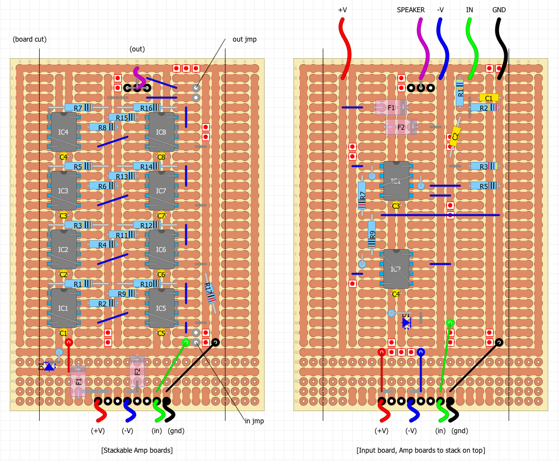
The boards will have a little cut off each edge as indicated on the drawing with the black vertical lines. The grey link wires represent connections on the bottom of the boards. There are also 2 jumpers on each amp board to allow you to disconnect the input and output of the board.
By making the boards stackable, you can simply keep adding boards until you have enough current output. It works out pretty cheap to make each board as all the components can be bought in bulk. Maybe as cheap as £4 a board.
I think I will make up for the cost of parts in the cost of time
I'll make an input board and a couple of amp boards and test. If successful, I will make another input board and eventually have 6 amp boards per channel. This will give me 96 OpAmps per channel and if we say each one can run comfortably at 25mA, then I will have 2.3A output capacity on each channel.
Copper Prototype PCB Stripboard/ Printed Circuit Board/Strip/Vero Board | eBay
The amp boards and the input boards are stackable using stackable headers. Here is the layout done in DIYLC:
The boards will have a little cut off each edge as indicated on the drawing with the black vertical lines. The grey link wires represent connections on the bottom of the boards. There are also 2 jumpers on each amp board to allow you to disconnect the input and output of the board.
By making the boards stackable, you can simply keep adding boards until you have enough current output. It works out pretty cheap to make each board as all the components can be bought in bulk. Maybe as cheap as £4 a board.
I think I will make up for the cost of parts in the cost of time
I'll make an input board and a couple of amp boards and test. If successful, I will make another input board and eventually have 6 amp boards per channel. This will give me 96 OpAmps per channel and if we say each one can run comfortably at 25mA, then I will have 2.3A output capacity on each channel.
Last edited:
The short coloured wires shown of the boards above are just an indication of what each pin of the headers are. Only the input board has any wires actually attached to it. The amp boards get there power and signal via the 8 pin stackable headers (represented on the drawing as black circles). The output from each board connects via the 3 pin stackable header at the top.
Using stackable headers means that you only have to fix the bottom board to the chassis, the rest will support themselves.
Using stackable headers means that you only have to fix the bottom board to the chassis, the rest will support themselves.
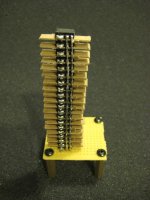
I started to make an op-amp "power amp" a couple years ago but got bored (overwhelmed?) will all my projects so it never got finished.
The original plan was 20x opa2134 per channel configured as unity buffers. In the pic I had one "PowerTower™" completed. The cardboard was intended as spacers to make an airflow gap between each op-amp. You can also see local ceramic decoupling caps and 10R output resistors on each output.
I think I just threw the whole thing in the trash a couple weeks ago.
Attachments
No, that channel still needed the driving op-amp installed for gain and feedback. I actually just found the stack broken in half in the trash bag I threw it in. Was cleaning up my junk room but the trash bag never actually made it to the curb (winter lazyness). Maybe I'll turn it into a headphone amp some day.
I have a couple hundred SOIC and TO-220 BUF634 that would probably be better suited for the task of a power amp anyway.
I have a couple hundred SOIC and TO-220 BUF634 that would probably be better suited for the task of a power amp anyway.
2 weeks ago I made for fun p2p headphone amp with multi opamps.
One channel:
Buffer - ne5532
Gain stage - op27 (AD)
Output stage - njm4556 x5
schematic
inputs and buffers
alps pot
gain stage and output buffers
Works very good.
One channel:
Buffer - ne5532
Gain stage - op27 (AD)
Output stage - njm4556 x5
schematic
inputs and buffers
alps pot
gain stage and output buffers
Works very good.
Last edited:
- Status
- This old topic is closed. If you want to reopen this topic, contact a moderator using the "Report Post" button.
- Home
- Amplifiers
- Chip Amps
- OpAmp power amp, would this work?