Shunting a DC blocking cap with a diode ruins the point. If you are using a split rail, why do you need a cap in the first place?
To make the amp unity gain at DC, and also ensure any DC errors aren't amplified.
More Daniel science?..........................In a Split Rail example, and perhaps the NFB cap with diode protection applied, the third order harmonics with diode misfire in practical use, plus the possibility of bouncing offset are all possible annoyances. ............
what?diode misfire
Seriously, Dan is a smart guy. He DOES design chipamps after all, but he understands things in his own abstract associative way. Sometimes this earns him stern looks from engineers who "know better". I still find "diode misfire" to be hilarious though. I wonder if this applies to avalanche diodes.
More Daniel science?what?
i don't think the diode will be on in normal operation.
Unfortunately, typical design with undersized NFB cap looks exactly like a bass blocker with a diode clipper. If we happen to get clearer deeper bass and slightly worse treble after adding the diode, that indicates the cap is too small. Repairing the RC timing error will stop the misfire.
The #1 cause of misfire is datasheet authors who typically install overly small NFB cap values in their example schematics, resulting in a terrible example.
The #2 cause of misfire is assuming that the perfect transformer always maintains the power supply symmetry as perfectly as shown in the simulator.
The #3 cause of misfire is using a current reliant diode in a voltage reliant application, with unexpected threshold and 3rd order harmonic distortion.
Since the error is absent with your specs, this proves that your small signal specs are correct.
However, I was serious about the diode problems.
Used normally, a zener is designed for voltage precision despite variable current, aka doesn't misfire.
However, I've never tried the zeners forwards.
I've tried a series triple of BAT86 and I've tried a series pair of FR/MR, which is all predictable and quiet.
1n4148's are too loud. Question: Is there a commonly available Soft switch fast silicon diode for signal use?
The #1 cause of misfire is datasheet authors who typically install overly small NFB cap values in their example schematics, resulting in a terrible example.
The #2 cause of misfire is assuming that the perfect transformer always maintains the power supply symmetry as perfectly as shown in the simulator.
The #3 cause of misfire is using a current reliant diode in a voltage reliant application, with unexpected threshold and 3rd order harmonic distortion.
If an amplifier is tuned to AndrewT small signal specs, a diode clipped nfb cap will NOT misfire, since the current reliant knee voltage of the diode is not a problem in the absence of current. If zilch for current, the diode can't cause audible 3rd order harmonic distortion.More Daniel science? what?
Since the error is absent with your specs, this proves that your small signal specs are correct.
I think that post #6 (battleship in a bathtub) is extremely hilarious, but nobody laughed.I still find "diode misfire" to be hilarious though. I wonder if this applies to avalanche diodes.
However, I was serious about the diode problems.
Used normally, a zener is designed for voltage precision despite variable current, aka doesn't misfire.
However, I've never tried the zeners forwards.
I've tried a series triple of BAT86 and I've tried a series pair of FR/MR, which is all predictable and quiet.
1n4148's are too loud. Question: Is there a commonly available Soft switch fast silicon diode for signal use?
This is excellent!bigwill said:I've got my basic PCB topology down. I don't know if it'll fit in a tin yet. I think it will.
Last edited:
I have a TDA4935 it only uses about 10 components to make a stereo 15 watt per channel amp... Not sure if it would fit in a tin, or how hot it would get, mainly because i have no idea what i'm doing lol, but i might give it a go.
Got no idea how to post image from pc so i cant show schematic!
Got no idea how to post image from pc so i cant show schematic!
Minty fresh breath is not required.Well, I think I've finished my PCB design, and I've found an old tobacco tin (not mine, I have never smoked!). Hopefully this doesn't break the rules")
Is the alternative tin approximately similar size to the average mint tin?
TDA4935. . . a bus, truck, "18 Wheeler" chip! Yes, it is designed to work within small metal enclosures--a truck radio in a hot dash. That chip is surprisingly fast.I have a TDA4935 it only uses about 10 components to make a stereo 15 watt per channel amp... Not sure if it would fit in a tin, or how hot it would get, mainly because i have no idea what i'm doing lol, but i might give it a go. Got no idea how to post image from pc so i cant show schematic!
Schematic
Attachments
Last edited:
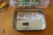
That looks nice, except that you might want to round off the sharp corners on some of those traces.Here's one channel trial fitted in a tin
That looks nice, except that you might want to round off the sharp corners on some of those traces.
I have my PCB transfer technique pretty good at this point - I shouldn't think it would be an issue. The traces aren't that thin
I'm going to stock up on some BC456 / 556 transistors (I seem to be getting pretty terrible rail sticking at 20khz with 2n3904/6s, if anyone can explain as to why this is I would appreciate it!)
I also need to order some PCB standoffs and some other bits and pieces. Don't worry - I'm not pouring money into this - it will be part of a routine component order.
I also need to order some PCB standoffs and some other bits and pieces. Don't worry - I'm not pouring money into this - it will be part of a routine component order.
Look at your schematic here.
http://www.diyaudio.com/forums/chip...in-class-aa-class-ab-class-b.html#post3253375
When Q5 is saturated, Q11 drives through it's base. Now current is coming into Q5's collector instead of going out. This reverses the gain of the amp and you get positive feedback instead of negative feedback. In a non-buffered VAS this is not a problem because the LTP cannot drive Q5's base hard enough to cause major sticking. But the buffer allows indefinite drive into saturation. You can improve this behavior by adding a schottkey diode between Q5's collector and Q11's base. This will short the VAS before Q5 saturates and prevent major positive feedback.
Also, that TIP pair is the absolute worst set of outputs you can use for a CFP at low bias. The Ft is 3MHz at 500mA. Probably 20KHz at 3mA!!! Try an MJE150xx pair, that will be better.
Check that the current through the miller cap at 20KHz isn't so much it clips the LTP.
Last edited:
Thanks for that keantoken, a diode worked beautifully (in simulation). What was happening, on further investigation, which in hindsight should have been obvious, was this: The VAS transistor wasn't running out of current to source out the collector - it was finding LOTS - happily supplied through the base of the NPN driver! With the output transistor saturated, it was able to pull a further 200mA or so. Spikes of 200mA through the VAS (which was essentially trying to drive the load!) of course upset the feedback loop, causing huge downward spikes when the death-grip from the VAS-buffer was finally released.
The diode of course provides local feedback to the VAS buffer / LTP output when the output gets to within 0.6V of the rail (which seems to be enough to catch it from trying to ram current into the base of the driver!)
The diode of course provides local feedback to the VAS buffer / LTP output when the output gets to within 0.6V of the rail (which seems to be enough to catch it from trying to ram current into the base of the driver!)
- Status
- This old topic is closed. If you want to reopen this topic, contact a moderator using the "Report Post" button.
- Home
- Amplifiers
- Chip Amps
- Contest: Linear Power Amp in a mint tin (class Aa, class AB, or class B)