since i've blown two of my bridged modules because of accidental shorting of the tab to casing (which in turn burned my speakers connected to it), i'm considering of rebuilding the other modules with speaker protection similar to the one used in myref into it.
anybody could advice me on how to increase the sensitivity of the protection circuit like the one below?
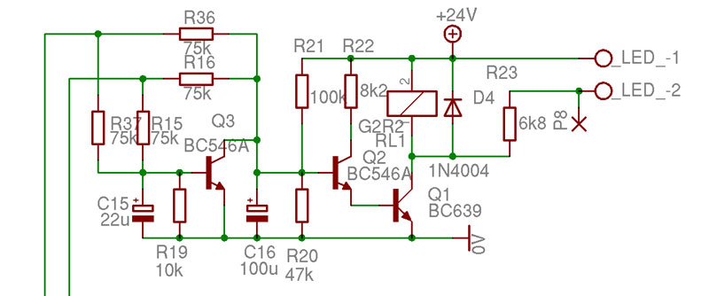
this is part of the miniref schematic, which is similar to the one used in my ref.
with the current component value, it triggers at about 4v something. could it be made to trigger at say around 1v? any advice/suggestion/criticism would be much appreciated.
anybody could advice me on how to increase the sensitivity of the protection circuit like the one below?
this is part of the miniref schematic, which is similar to the one used in my ref.
with the current component value, it triggers at about 4v something. could it be made to trigger at say around 1v? any advice/suggestion/criticism would be much appreciated.
thanks for the reply andrew. well frankly i would, if i could. but i couldn't. space is a luxury that i don't have. a very basic protection is still better than no protection. lesson learned. a pricey one at that.the circuit around Q3 must be replaced.
Better to start with a proper protection/delay circuit rather than this VERY basic version compromised by trying too hard to minimise the number of components.
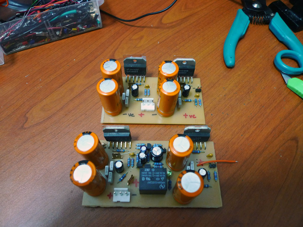
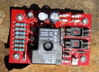
the original modules have a size of 5cm x 9cm. i managed to squeeze the protection circuit inside while increasing the width another 1 cm to 5cm x 10cm
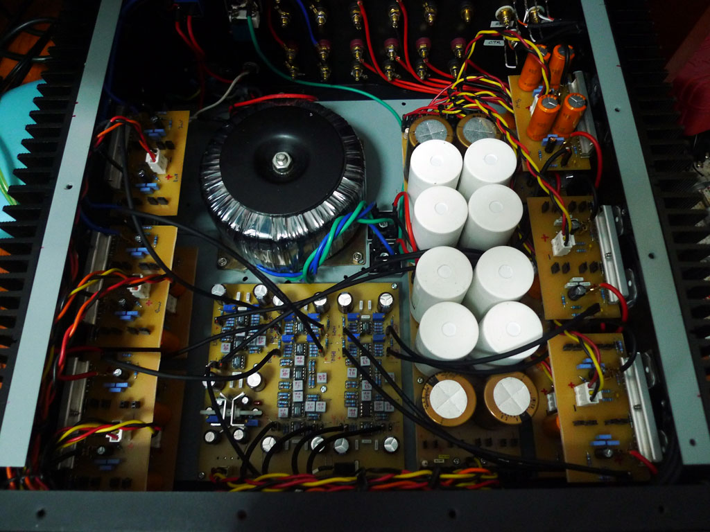
as the original amp are arranged to accommodate amp modules with the original size of 5x9, large amount of size increase would mean that i have to retrofit most of the boards back.
as you can see, it's already packed as it is. my options are currently limited to the simple protection circuit.
the circuit around Q3 must be replaced.
Better to start with a proper protection/delay circuit rather than this VERY basic version compromised by trying too hard to minimise the number of components.
Sorry to bump an old thread. Any schematic / parts suggestions?
Thanks Joseph. I'll try that. What about C12? Should I increase it too? I'd really like some huge delay so that I can hear the relay sound separate from the turn on switch (which itself makes a huge "tuck" sound).
Uhm.. afraid it's not really a good idea..
Turn on - turn off delay are connected. The circuit is tuned to not react too fast but still fast enough so as not burn down your speaker..
In practice it turned out perfect. If you start to tune it be warned..
This circuit does not work for negative DC  I have used it and found the same problem, there is however a simple modification to improve it that I have found on the forum here : My_Ref Fremen Edition - Build thread and tutorial
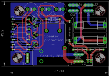
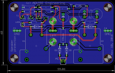
I made a PCB layout ( Very simple quasi complimentary MOSFET amplifier ), but I have to test it before to build it...
Marc
I have used it and found the same problem, there is however a simple modification to improve it that I have found on the forum here : My_Ref Fremen Edition - Build thread and tutorialI made a PCB layout ( Very simple quasi complimentary MOSFET amplifier ), but I have to test it before to build it...
Marc
The protection in the FE works fine. Larger caps will slow down the turn on/off a little.
I built a new amp and a fast on plug came loose from the power transformer while digging around after the initial shake out. DC offset would start around 0.64 volts and go up to 0.8 volts after warm up. Never tripped the relay.
Thought I had done some damage. Found the simple problem and all is well. Back to a couple mv of offset.
On the original schema DC offset will not activate the relay with less than about +6 to 8 VDC because or the resistor divider 75k or 100k / 10k and for a negative offset it doesn't work ! I have tested it on the attached module and redesigned it after the comments of Jac ( lehmanhill ) in the thread previously mentionned !
I will tell you the result when it will be tested
Marc
I will tell you the result when it will be tested
Marc
Attachments
- Status
- This old topic is closed. If you want to reopen this topic, contact a moderator using the "Report Post" button.
- Home
- Amplifiers
- Chip Amps
- Increasing MyRef speaker protection circuit sensitivity