Power Transformers
Daniel,
Here is a page from Digi-Key, the results of a search I made. It has some interesting results - for order quantity one, that is. Some reasonable prices also. The URL may look funny, but when I click on it, it goes to the correct page. If anyone has a problem, let me know and I can pm the table.
The page will be active for a while.
Power Transformers | Transformers | DigiKey
May you never suffer a cold solder joint
Resistor Photos
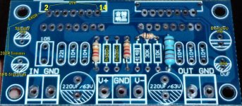
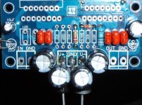
I'm putting together the other channel now. Here's what it looks like.
In the picture, it shows the feedback resistor (27K under-board and it shows the feedback-shunt resistors (680R+200R trimmer) under board.
The mute is simplified with "just 10k" as shown (22k also works fine). I used a little 1/8 watt resistor for the mute, however, a full size resistor can be used--it just stands up a little bit. The board's datasheet application for mute is more elegant while the amplifier is off. However, for mute I prefer just one resistor and omit the mute cap to simplify the power circuit for clearer sound while the amp is on. The difference is minor.
The Standby with 22k resistor and 10u cap is done per the datasheet.
Attachments
Last edited:
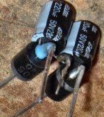
With that power supply voltage, you can use 50v or higher caps.. . . can I use 63V cap instead 100V caps, as supply is only 35V DC?. . .
P.S.
If using 28+28vac transformer, 63v caps may last longer.
However, if using 25+25vac transformer, 50v caps are fine.
Across every component that may have to pass a fault induced current.
eg. the NFB DC blocking cap. The resistor between Signal Ground and Power Ground. The resistor, if any, between Power Ground and Chassis.
It is also worth adding a single reverse biased diode across any component that could see a damaging reverse voltage.
eg, the output device, the smoothing capacitor, the power input to the amplifier.
AntiParallel Diodes prevent cap discharge from knocking out the inverting input, pin2
Signal:
AndrewT's figures for NFB-Shunt Cap size are correct, and this is easy to prove. If the cap size is chosen smaller than his examples, the antiparallel diodes will conduct pulses of DC offset, aka "offset bounce." However, if the cap size is at/near his examples, then the cap conducts the signal intact, leaving no extra/wasted voltage to switch on the diodes, and thus when the cap is at the size he recommends, offset does Not occur per the bass beat.
DC and error conditions:
A 1N4007 starts to switch on (stutters on) at about 0.47VDC. This might not be quite enough "leeway" for some slightly tilted rails and other error conditions that may or may not occur on some builds. Therefore, I'm going to show antiparallel diodes (0.47VAC) series to antiparallel diodes (0.47VAC) resulting in 0.94V tolerance. In this case, the NFB-Shunt Cap cannot charge up to more than 0.94V.
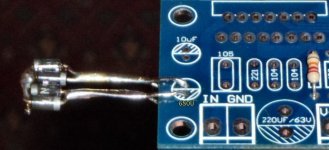
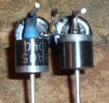
In the photo below I have:
Pin2, diode>|, diode>|, ground
Pin2, |<diode, |<diode, ground
And, in the photo below, I have left the pins quite long because I have several possible suitable caps to use for NFB-Shunt Cap and I'm going to "test drive" them in combination/conglomerate with a 1u or 0.47u electrolytic for treble bypass cap. Dual-layer boards are quite difficult to desolder and swap caps, so I've left some room to do that. The caps will quite easily straddle the diode pins. That might also be useful in case your caps are too big to fit on the board.
Signal:
AndrewT's figures for NFB-Shunt Cap size are correct, and this is easy to prove. If the cap size is chosen smaller than his examples, the antiparallel diodes will conduct pulses of DC offset, aka "offset bounce." However, if the cap size is at/near his examples, then the cap conducts the signal intact, leaving no extra/wasted voltage to switch on the diodes, and thus when the cap is at the size he recommends, offset does Not occur per the bass beat.
DC and error conditions:
A 1N4007 starts to switch on (stutters on) at about 0.47VDC. This might not be quite enough "leeway" for some slightly tilted rails and other error conditions that may or may not occur on some builds. Therefore, I'm going to show antiparallel diodes (0.47VAC) series to antiparallel diodes (0.47VAC) resulting in 0.94V tolerance. In this case, the NFB-Shunt Cap cannot charge up to more than 0.94V.
I'll show twice that much.Tomom said:Daniel, please can you show where and how do you connect that anti-parallel pair of 1N4007..thanks.
In the photo below I have:
Pin2, diode>|, diode>|, ground
Pin2, |<diode, |<diode, ground
And, in the photo below, I have left the pins quite long because I have several possible suitable caps to use for NFB-Shunt Cap and I'm going to "test drive" them in combination/conglomerate with a 1u or 0.47u electrolytic for treble bypass cap. Dual-layer boards are quite difficult to desolder and swap caps, so I've left some room to do that. The caps will quite easily straddle the diode pins. That might also be useful in case your caps are too big to fit on the board.
Attachments
Last edited:
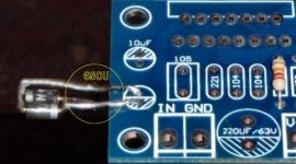
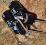
Here's a compact way to get a 680u and antiparallel diodes installed.Daniel, please can you show where and how do you connect that anti-parallel pair of 1N4007..thanks.
Treble bypass cap, such as 1u or 0.47u electrolytic, will fit easily under-board.
Attachments
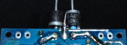
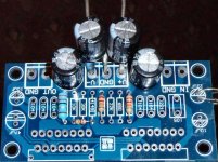
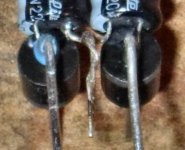
Power photo bonanza. . . Shield power with 6A05's and 440u.
On my board, I have a parallel pair of 220u caps and a standard diode, per each rail.
There was one caveat--a ground trace on top of the board, in front of the V- terminal, needed some extra insulation, just to be sure. So, that little blue bit in the photos is a scrap of heat shrink tubing.
These photos with 440u and 6A05 per rail, are just an expansion of the previous effort. Substitutes for 6A05 include 6A01, 6A02, 10A05, 10A01, 10A02. I got my 6A05's from the radio shack store. The larger voltage drop can allow up to 660u per rail and still sounds like small caps, all fresh and clean. Curiously the greater voltage drop in combination with the greater capacitance results in More useful audio power. I could not possibly explain why, except that the amp behaves as if the proportion of useful power is greater. A real engineer is needed before an explanation makes sense.
Functional Parameters:
If what is shown in the photos is too much work, simple 220u and MBR1635 (or MBR1645) per rail works great, is low loss, and still performs on stereo separation.
Works vs doesn't work:
220u per rail and 6A05 works. (0.65vfw, 100u~660u range)
440u per rail and MBR1645 doesn't work. (0.25vfw, 100u~220u range)
In these parameters I see that the bigger capacitance causes the need of the bigger voltage drop--the bigger voltage drop does Not cause the need of bigger capacitance. So, if you're using substitute parts, perhaps these parameters will help.
Notes:
Whatever diodes you really hate for discrete bridge rectifiers (switching) can be used for this forward biased (non-switching) application, since the usage is much different.
Reverse voltage tolerance is not used by this application; however, for forward bias applications, low voltage diodes (35v~100v) will work better than high voltage diodes (400v~1000v) and you can see why if you look at your diode's datasheet forward voltage drop graph. Choose a diode with a forward voltage drop per current graph that looks like this: "|" not like this: "/".
If driving heavy loads at full tilt for long duration at full blast, you might rather have 10A05's which are far stronger than the amplifier.
Estimate: Apparently, if using the very bottom of the chart (stutter/first switch on, smallest figure) one could multiply the diode's smallest forward voltage drop in the diode's datasheet by 1000 to approximate the maximum capacitance per rail it can shield for the amplifier board. The actual figure may be somewhat less than 1000, so be sure to leave room (voltage drop) for the application to work.
A simpler (220u+MBR) version will work for this board is minimal effort and sounds great.
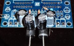
However, I'm doing this larger (440u+6A05) version because it further reduces the need of compensation (in some way that I do not understand) and the greater tolerance may allow the gain to be dialed even lower. Orthodox: It may do nothing other than promote greater stereo separation, because it is Virtual Dual Mono, aka Dualmono/Monoblocs with only 1 transformer, only 1 power supply board. Unorthodox: The 6A05's have allowed using larger capacitance on the amplifier board without also incurring either extra heat or dull sound that can be observed if the diodes are omitted. So, you can see why I used the diodes. I don't know exactly how this works, but it is reliable and the function is fantastic. I don't have any more data on this, so here's the photos. . .
On my board, I have a parallel pair of 220u caps and a standard diode, per each rail.
There was one caveat--a ground trace on top of the board, in front of the V- terminal, needed some extra insulation, just to be sure. So, that little blue bit in the photos is a scrap of heat shrink tubing.
These photos with 440u and 6A05 per rail, are just an expansion of the previous effort. Substitutes for 6A05 include 6A01, 6A02, 10A05, 10A01, 10A02. I got my 6A05's from the radio shack store. The larger voltage drop can allow up to 660u per rail and still sounds like small caps, all fresh and clean. Curiously the greater voltage drop in combination with the greater capacitance results in More useful audio power. I could not possibly explain why, except that the amp behaves as if the proportion of useful power is greater. A real engineer is needed before an explanation makes sense.
Functional Parameters:
If what is shown in the photos is too much work, simple 220u and MBR1635 (or MBR1645) per rail works great, is low loss, and still performs on stereo separation.
Works vs doesn't work:
220u per rail and 6A05 works. (0.65vfw, 100u~660u range)
440u per rail and MBR1645 doesn't work. (0.25vfw, 100u~220u range)
In these parameters I see that the bigger capacitance causes the need of the bigger voltage drop--the bigger voltage drop does Not cause the need of bigger capacitance. So, if you're using substitute parts, perhaps these parameters will help.
Notes:
Whatever diodes you really hate for discrete bridge rectifiers (switching) can be used for this forward biased (non-switching) application, since the usage is much different.
Reverse voltage tolerance is not used by this application; however, for forward bias applications, low voltage diodes (35v~100v) will work better than high voltage diodes (400v~1000v) and you can see why if you look at your diode's datasheet forward voltage drop graph. Choose a diode with a forward voltage drop per current graph that looks like this: "|" not like this: "/".
If driving heavy loads at full tilt for long duration at full blast, you might rather have 10A05's which are far stronger than the amplifier.
Estimate: Apparently, if using the very bottom of the chart (stutter/first switch on, smallest figure) one could multiply the diode's smallest forward voltage drop in the diode's datasheet by 1000 to approximate the maximum capacitance per rail it can shield for the amplifier board. The actual figure may be somewhat less than 1000, so be sure to leave room (voltage drop) for the application to work.
A simpler (220u+MBR) version will work for this board is minimal effort and sounds great.
However, I'm doing this larger (440u+6A05) version because it further reduces the need of compensation (in some way that I do not understand) and the greater tolerance may allow the gain to be dialed even lower. Orthodox: It may do nothing other than promote greater stereo separation, because it is Virtual Dual Mono, aka Dualmono/Monoblocs with only 1 transformer, only 1 power supply board. Unorthodox: The 6A05's have allowed using larger capacitance on the amplifier board without also incurring either extra heat or dull sound that can be observed if the diodes are omitted. So, you can see why I used the diodes. I don't know exactly how this works, but it is reliable and the function is fantastic. I don't have any more data on this, so here's the photos. . .
Attachments
Last edited:
Thank you!The local decoupling is working better and thus the amplifier sounds better.
Well, if the 35v cap actually gets 35v, then it may last only a few hours. So, perhaps we'd like to use 50v or 63v caps for the bootstrap cap to last much longer. The value of the bootstrap cap can be either 68u or 100u for the parallel amp.
P.S.
Input cap and nfb-shunt caps can be low voltage models, if desired.
P.S.
Input cap and nfb-shunt caps can be low voltage models, if desired.
Daniel,
Here is a page from Digi-Key, the results of a search I made. It has some interesting results - for order quantity one, that is. Some reasonable prices also. The URL may look funny, but when I click on it, it goes to the correct page. If anyone has a problem, let me know and I can pm the table.
The page will be active for a while.
Power Transformers | Transformers | DigiKey
May you never suffer a cold solder joint
Wouldn't you want closer to a 5 Amp transformer for 1 of these kits? Around 200VA per kit? All I see here are mostly 1 Amp transformers, I don't think they are enough??? I see Daniel suggests the 300VA from Antek.
Amplifiers work with a very wide range in transformer power.
The usual size for normal good value and good performance is VA from one times to two times the total maximum output power.
A dual 60W chipamp will work with a 120VA to 240VA transformer.
Going to 3times gains very little in performance, increasing this to 4times gains even less.
I generally recommend a minimum of 160VA due to the very high regulation of smaller transformers.
- Home
- Amplifiers
- Chip Amps
- TDA7293 Parallel kit from ebay (modular/slave style, no lossy emitter resistors)