The ballpark for Stereo amplifier (1 transformer, 2 channels)
Here are some transformer options:
18+18vac 300va about 27 watts (or ~50w to 4R)
22+22vac 350va
25+25vac 400va (I'm using this one)
28+28vac 450va about 70 watts per channel to 8R
These all have the amperage high enough to keep the power board caps full/working correctly for audio. That faster charge lets the amp run closer to the rails without early clipping.
Power boards. . .
Small:
Minimum suggested capacitance is 4 of 3300u 50v caps per rail, 13,200u per rail.
Medium:
With the price break at Mouser on Nichicon occuring at 10 caps (5 of 3300u caps per rail) you might as well step it up to 16,500u per rail and this medium size is what I use (and it near-matches specs with Tom's more practical examples).
Large:
The transformers above are all strong enough to charge up 19,200u per rail in-between bass beats of rather fast music playing loud. See Bob's power supply example for this size supply (in his TDA7294 thread).
Note:
The above specs aren't budget/production/retail specs at all; but, I believe we would likely choose them for personal diy use.
Alignment for production/budget rig:
300va 25+25vac transformer, TWO bridge rectifiers, and 13200u per rail simple supply.
As small as 250va may be used, but I'd prefer better than that on a stereo build.
An even smaller transformer may be used, with the caveat that it won't make as much power.
(but if you want more power instead, see post #41 just above)
Last edited:
Thank you Andrew (great explanation btw), AJT (no sinewaves except to test limits with minimally), and Daniel. I was thinking of only using one of these chips for my subwoofer and a pair of LM3886's for my left and right for a 2.1 setup (maybe 3886's are overmatched for the 7293 but I can live with that/tweak the volume down a bit on them), so it appears 200VA should be plenty for 1 of these 7293 kits by itself.
Right now I have a 20+20V mega amperage transformer that I will start with, I know its around the sweet spot for 4 ohm 3886, but I may do 8 ohm instead in which I can beef up the trafo voltage to more match the 7293 at 4 ohm. I just wanna get this thing started with what I have and work up from there, so this is all great info on this kit! Keep it up Daniel! Soon as my kit comes in for the preamp, I can get this thing rolling and work on the PSU as I go.
Right now I have a 20+20V mega amperage transformer that I will start with, I know its around the sweet spot for 4 ohm 3886, but I may do 8 ohm instead in which I can beef up the trafo voltage to more match the 7293 at 4 ohm. I just wanna get this thing started with what I have and work up from there, so this is all great info on this kit! Keep it up Daniel! Soon as my kit comes in for the preamp, I can get this thing rolling and work on the PSU as I go.
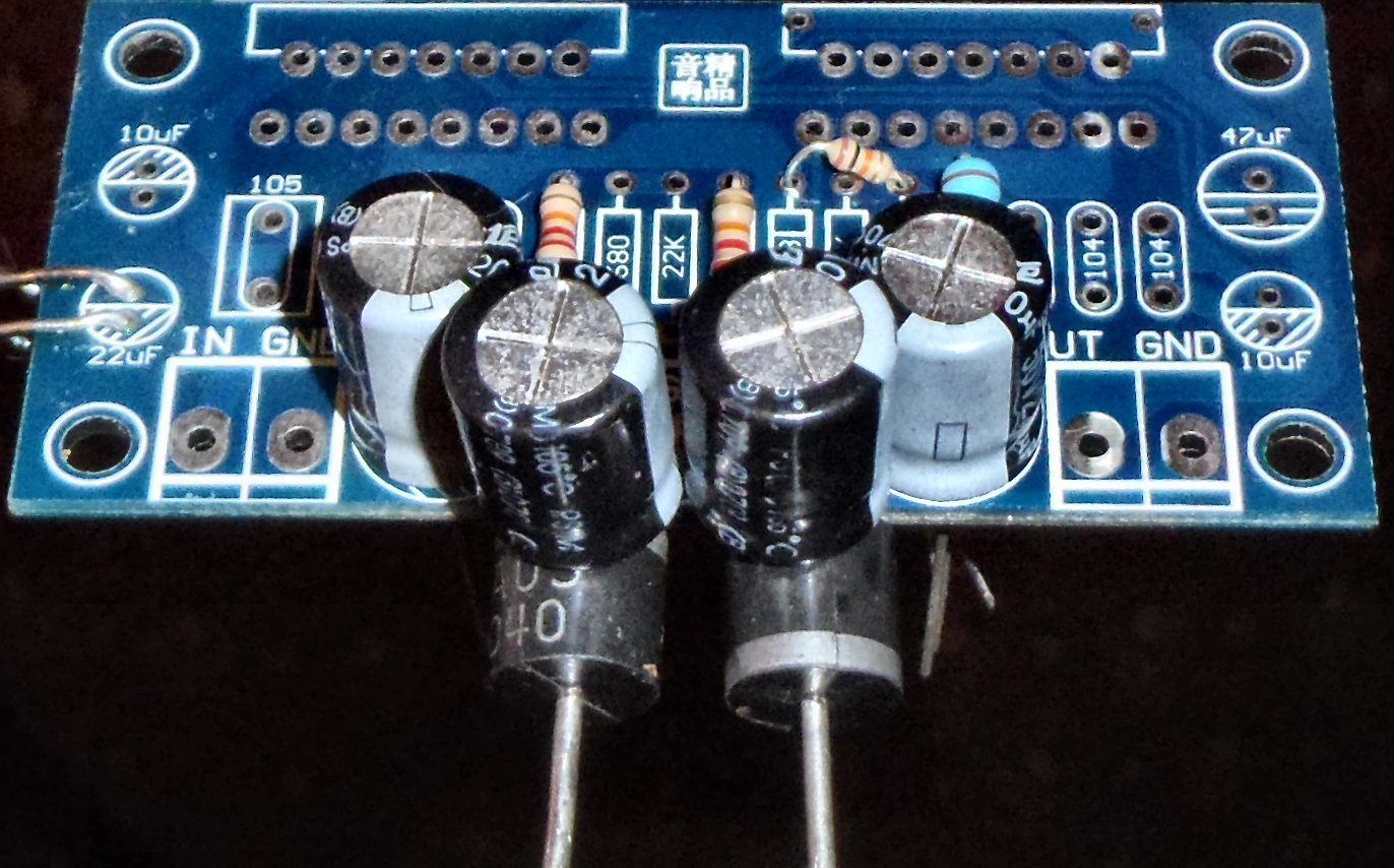
To avoid bad tone, some inductance must be removed by Moving at least 1 resistor.
This was posted earlier, however, it does contain a top priority layout fix.
I'm not talking about the feedback resistor, but rather its partner, the feedback-shunt resistor really must be moved. See the left side of the board, the Feedback-Shunt resistor, 680R+200VR (startup value Total is about 727R).
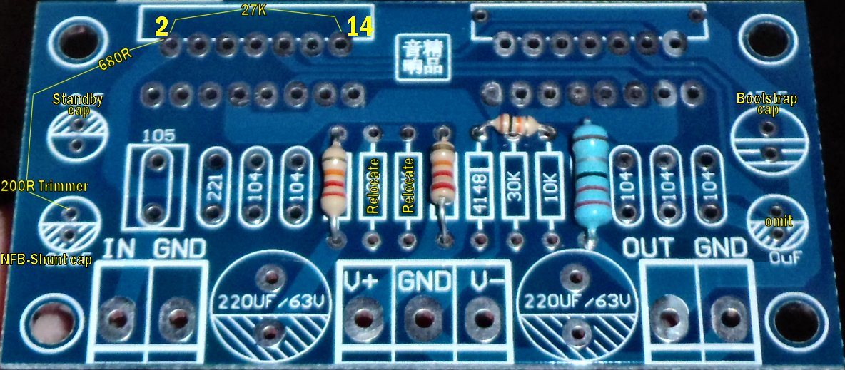
The most important thing about this photo is that the feedback-shunt resistor has been relocated from its inadvisable yet decorative location. . . to a much more direct route instead.
The photo shows the Feedback-Shunt resistor (680R + 50VR) directly from Pin2 to the NFB-Shunt Cap. This change in location to a direct route has removed an extraneous inductor (the overlong trace).
The fix is this: Shortest, most direct route, is least inductance.
This one easy fix will do more than any amount of labor or expense with signal parts selection. Even the most expensive audiophile cap can perform like a really bad cap if when in series to excessive inductance. Specifically, there's no need to play with audiophile or bypass caps until after the resistor has been moved off of the overlong trace, and relocated to direct route instead. After moving the feedback-shunt resistor as shown in the photo, then your signal capacitor Brands&Bypass play, can work as expected.
Basically:
Please don't attempt captweak labor, or other fine tuning, before moving the resistor(s).
Please move resistor(s) first, since layout is more important than capacitor brand names.
P.S.
I don't regret the miniscule labor it takes to move one or two resistors on an otherwise excellent board. The board designer, is probably a genius. Doing just perfectly well on ST's 30 pinout chip challenge, and a very nicely performing power layout too, and then getting only one of the easiest things off the mark, is really genius-like behavior similar to making practical nuclear fusion work just fine and then going to the grocery store while wearing one black shoe and one white shoe.")
Can somebody read and translate that signature? Because I like the power circuit's performance, I would like to check out and probably use whatever else may be made by this particular board designer.
This was posted earlier, however, it does contain a top priority layout fix.
I'm not talking about the feedback resistor, but rather its partner, the feedback-shunt resistor really must be moved. See the left side of the board, the Feedback-Shunt resistor, 680R+200VR (startup value Total is about 727R).
The most important thing about this photo is that the feedback-shunt resistor has been relocated from its inadvisable yet decorative location. . . to a much more direct route instead.
The photo shows the Feedback-Shunt resistor (680R + 50VR) directly from Pin2 to the NFB-Shunt Cap. This change in location to a direct route has removed an extraneous inductor (the overlong trace).
The fix is this: Shortest, most direct route, is least inductance.
This one easy fix will do more than any amount of labor or expense with signal parts selection. Even the most expensive audiophile cap can perform like a really bad cap if when in series to excessive inductance. Specifically, there's no need to play with audiophile or bypass caps until after the resistor has been moved off of the overlong trace, and relocated to direct route instead. After moving the feedback-shunt resistor as shown in the photo, then your signal capacitor Brands&Bypass play, can work as expected.
Basically:
Please don't attempt captweak labor, or other fine tuning, before moving the resistor(s).
Please move resistor(s) first, since layout is more important than capacitor brand names.
P.S.
I don't regret the miniscule labor it takes to move one or two resistors on an otherwise excellent board. The board designer, is probably a genius. Doing just perfectly well on ST's 30 pinout chip challenge, and a very nicely performing power layout too, and then getting only one of the easiest things off the mark, is really genius-like behavior similar to making practical nuclear fusion work just fine and then going to the grocery store while wearing one black shoe and one white shoe.
Can somebody read and translate that signature? Because I like the power circuit's performance, I would like to check out and probably use whatever else may be made by this particular board designer.
Last edited:
Hi, I am thinking about building one of these (Stereo for guitar effects) This is my first build of this type as I build tube amps. I am interested in a small compact amp design like this that can keep up in a band environment, but with high quality tone. I have various preamp ideas based on the ROG (www.runoffgrove.com Fet preamp emulators) that can be easily swapped out. Will this build be powerful enough without any harsh clipping in a band situation? We are not playing Head-Banger volumes, we play anything from Classic Rock, Blues, Country Jazz and Fusion, some Prog-Rock etc. but I have been using 50-100 watt tube amps. Any suggestions, direction would be really appreciated on this, hopefully I can get it right the first time :^) Thank you for this wonderful info here!
Ed
Ed
Last edited:
Is this similar to the build you did or is it not really what I want for guitar applictaion? Looks good :^)
Thanks Ed
TDA7293 Stereo Power Amplifier Board 80W 80W DIY Amp Board | eBay
Thanks Ed
TDA7293 Stereo Power Amplifier Board 80W 80W DIY Amp Board | eBay
Sorry for all my excited postings here! Here is what I think you have posted:
TDA7293 x2pcs 170W Mono Amplifier Board Kit 29 | eBay
It looks like it.
TDA7293 x2pcs 170W Mono Amplifier Board Kit 29 | eBay
It looks like it.
Hi Ed!Hi, I am thinking about building one of these (Stereo for guitar effects) This is my first build of this type as I build tube amps. I am interested in a small compact amp design like this that can keep up in a band environment, but with high quality tone. I have various preamp ideas based on the ROG (www.runoffgrove.com Fet preamp emulators) that can be easily swapped out. Will this build be powerful enough without any harsh clipping in a band situation? We are not playing Head-Banger volumes, we play anything from Classic Rock, Blues, Country Jazz and Fusion, some Prog-Rock etc. but I have been using 50-100 watt tube amps. Any suggestions, direction would be really appreciated on this, hopefully I can get it right the first time :^) Thank you for this wonderful info here!
Ed
The amplifier is quite powerful, and I didn't notice any clipping when testing that out. However, tube amp features are not packed into the tiny yellow mailer with the chip amp. For solid state including chip amplifiers too, the tube amp features are available as add-ons. Fet triode substitute effects work about half as well as real triodes, but there's a closer match for everything else.
Boards:
You could go to ebay.com and look up item # 190862927141 for stereo or item # 151069927624 for mono.
Thanks! That's a good idea! Well, the SMD is a good idea.
However, I'm not doing board design at this time because some of the accessories (and I love accessories) are TBD (not yet built). In any case, if you wanted it streamlined and inexpensive, then you probably want the boards listed in post#1 of this thread.
A more minimal mod version is possible, for a much easier assembly of something that was already easy. And, the performance is almost as good (very similar). Is that of any interest?
Thanks! That's a good idea! Well, the SMD is a good idea.
However, I'm not doing board design at this time because some of the accessories (and I love accessories) are TBD (not yet built). In any case, if you wanted it streamlined and inexpensive, then you probably want the boards listed in post#1 of this thread.
A more minimal mod version is possible, for a much easier assembly of something that was already easy. And, the performance is almost as good (very similar). Is that of any interest?
Hi,
I don't really mind paying for an optimized PCB since I like a clean look, even though it will be hidden in a chassis. If someone has the skills and is interested in doing a PCB layout using part SMD and through hole it would be great!
Thanks
Do
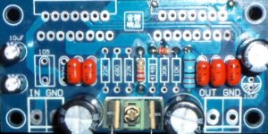
Optionally, MUR diode can be used. Or MURS diodes with the nicely insulated tab may be even better.If what is shown in the photos is too much work, simple 220u and MBR1635 (or MBR1645) per rail works great, is low loss, and still performs on stereo separation.
Clean look? Okay. See photo. It is an illustration. But it shows a simplified means to get nearly the same performance, and that clean look too.pinnocchio said:I don't really mind paying for an optimized PCB since I like a clean look, even though it will be hidden in a chassis. If someone has the skills and is interested in doing a PCB layout using part SMD and through hole it would be great!
Attachments
Last edited:
Class G, actually Manual Class G and a gain switch too.
Power
The easy way for Class G is to arrange a sturdy DPDT switch to change the transformer to half voltage. This is done by switching the dual primaries toroid transformer to series or parallel for voltage change. For example, my 28+28vac transformer changes to a 14+14 transformer. In this case, the switch changes the amplifier to either 70W for high power fun or 14W for energy saving normal use.
I'm currently looking for an "Off, On, On" switch that could, if the center position is low power, perform a rudimentary soft start, since it always goes to low before it goes to high.
Gain
This also gives the possibility to use a small DPST for reducing the gain on the amplifier boards for whenever they're set to low voltage. Yes, these TDA7293's can run lower gain and image well, when used as 14W amplifiers. So, this additional switch is also low-high. High would be a gain of 38X, but low could simply engage additional negative feedback. There's a few different options to explore, but they are switchable. The amp likes lower gain when run lower voltage, and it likes higher gain when run higher voltage. So, two different settings are probably necessary.
Results
Given these two switches (one for power, another for gain), you can have option of a pretty little 14W amp with the switches set on low or flip both switches to high for a highly palatable tone at high power.
4 ohms
With 4 ohm speakers, the power output is about 25 watts per channel on low or 90 watts per channel on high.
Last edited:
Cutting the power voltage in half causes the need of compensation readjustment that may could be done by setting lower gain. But I really wonder. . . How do you recommend doing the cabling for switchable gain?would the chipamp compensation need to be changed when the gain is changed?
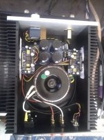
Here is mine
Hi Folks,
Here is mine. I bought PCB, power supply PCB and case from eBay. Case came with power, speaker and RCA connectors. Built according to schematics except Rf, Ri changed to 47k, 1,5k - Feedback capacitor changed from 22uf to 220uf and the bootstrap to 150uf.
It sounds wonderful, in the pictures it is sitting on top of VSSA. Main differences between these two are - VSSA is bit more transparent you can perceive the layers of sound. TDA7293 amp has bit more punch in the bass region. We can find the difference between these amps when we do A/B testing. Otherwise we can equally enjoy the sound of both these amps and you forget the differences.
Finally, I would like to Chinese sellers on eBay, without them I couldn't build this high quality amp with such a low price. I do remember how hard to get the PCBs, only way is to order in bulk. Forget about the chassis, there was no place to buy a good chassis at reasonable prices.
Attachments
That is a beautiful job on the build!
However, I do have some comments on the electronics.
I see a center tap configuration, which has an opportunity.
Transformer reacting with your bridge rectifier makes noise that can cause masking. But we could hinder the problem. One variable RC made with a 2.2uF polyester cap series to a 50 ohm variable resistor can be hooked up from ~ to ~ (across the transformer) to dampen that area so that the high pitched racket doesn't put masking into the amplifier power circuit. This RC doesn't attach to ground. Turn the dial for best treble imaging clarity.
After that. . .
It may be important to note that, with a chip amp, the entire amplifier board is the small signal area.
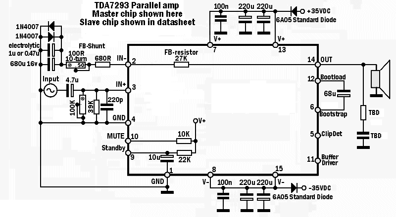
This photo matches up with the schematic at Post#1.
The photo shows amplifier board power decoupling forced to work, which is the most certain way to guarantee that it does work. The diodes also provide virtual dual mono stereo separation since each amplifier board has a little bit of somewhat "private" power.
All of the above is good for clarity and imaging.
These diodes are runing on only DC (you Do still use a power supply board). Suitable diodes include standard silicon diodes like 6a05 (at the radio shack) 6a01, 6a02, 10a05, 10a01, 10a02 and similar. This small voltage drop doesn't decrease usable audio output power at all, but it will do less constant power, more peak power, which is more useful, more dynamic and more lifelike.
Also,
This is a gain compensated amplifier and it needs to be set precisely; so, I would suggest to use a multi-turn variable resistor at feedback-shunt resistor. In your example with 1.5k, you can use 1k multi-turn trimmer series to 510 ohm resistor. The ideal location is very close to and directly between the nfb-shunt cap and pin2 of the master chip (which are conveniently close to each other). My schematic has this adjustable gain dial because the ideal compensation (and therefore ideal gain) depends on the power supply voltage used. The sweet spot is very narrow and nearly impossible to get with fixed resistor values. Consider it an audio quality dial.
P.S.
Just like a discrete amp, the chip amp can benefit from cleaner power and precision compensation.
After completing the work, then it could then be more interesting to do the A-B comparisons.
I hope this information helps.
However, I do have some comments on the electronics.
I see a center tap configuration, which has an opportunity.
Transformer reacting with your bridge rectifier makes noise that can cause masking. But we could hinder the problem. One variable RC made with a 2.2uF polyester cap series to a 50 ohm variable resistor can be hooked up from ~ to ~ (across the transformer) to dampen that area so that the high pitched racket doesn't put masking into the amplifier power circuit. This RC doesn't attach to ground. Turn the dial for best treble imaging clarity.
After that. . .
This is for the layers of sound, aka open sound.. . . it is sitting on top of VSSA. Main differences between these two are - VSSA is bit more transparent you can perceive the layers of sound. TDA7293 amp has bit more punch in the bass region. We can find the difference between these amps when we do A/B testing. Otherwise we can equally enjoy the sound of both these amps and you forget the differences.
It may be important to note that, with a chip amp, the entire amplifier board is the small signal area.
This photo matches up with the schematic at Post#1.
The photo shows amplifier board power decoupling forced to work, which is the most certain way to guarantee that it does work. The diodes also provide virtual dual mono stereo separation since each amplifier board has a little bit of somewhat "private" power.
All of the above is good for clarity and imaging.
These diodes are runing on only DC (you Do still use a power supply board). Suitable diodes include standard silicon diodes like 6a05 (at the radio shack) 6a01, 6a02, 10a05, 10a01, 10a02 and similar. This small voltage drop doesn't decrease usable audio output power at all, but it will do less constant power, more peak power, which is more useful, more dynamic and more lifelike.
Also,
This is a gain compensated amplifier and it needs to be set precisely; so, I would suggest to use a multi-turn variable resistor at feedback-shunt resistor. In your example with 1.5k, you can use 1k multi-turn trimmer series to 510 ohm resistor. The ideal location is very close to and directly between the nfb-shunt cap and pin2 of the master chip (which are conveniently close to each other). My schematic has this adjustable gain dial because the ideal compensation (and therefore ideal gain) depends on the power supply voltage used. The sweet spot is very narrow and nearly impossible to get with fixed resistor values. Consider it an audio quality dial.
P.S.
Just like a discrete amp, the chip amp can benefit from cleaner power and precision compensation.
After completing the work, then it could then be more interesting to do the A-B comparisons.
I hope this information helps.
Last edited:
Hi Daniel,
Thank you for detailed feedback and suggestions for improvement. I'll go through them and implement them at my free time and surely post my findings in this thread. I can tell you this seems so simple but it is a serious amplifier that can easily compete with other high end ones.
Thanks
Thank you for detailed feedback and suggestions for improvement. I'll go through them and implement them at my free time and surely post my findings in this thread. I can tell you this seems so simple but it is a serious amplifier that can easily compete with other high end ones.
Thanks
- Home
- Amplifiers
- Chip Amps
- TDA7293 Parallel kit from ebay (modular/slave style, no lossy emitter resistors)