First, allow me to apologise in advance for the length of this post.
Having recently built myself a slightly modified CMoy amp, I've been curious to know if I can take that knowledge and make something better suited to my purposes. These purposes are as follows:
- Must operate from 5VDC or 12VDC (supply is a PC PSU, thus PWM)
- Must be sourced from local supplier (Jaycar)
- Must be relatively straight forward (MOSFETs are what now?)
- Must work with low impedance headphones (64Ω Sennheiser HD 280 Pro)
- Must sound "good enough"
That last one is perhaps the easiest. I have no CRO or other testing equipment - just a hand-held multimeter and my two ears, and one of those ears is for display purposes only. It doesn't have to test like the greatest thing ever built, nor reach un-Godly volumes, so long as it's enough all around.
Credit goes to Chu Moy, Tangent and NwAvMan. This design is based on my interpretation of the work of the three of them (the CMoy and Objective2). Since my field is more electrics (auto electrics if I'm honest) than electronics, I suspect I've gotten more than a few things wrong - hence this thread.
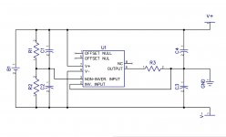
Power (attachment 1 - power.jpg):
- B1 = 5VDC (hopefully)
- C1/C2 = 220pF/50V Ceramic
- C3/C4 = 470μF/16V L/ESR Electrolytic
- R1/R2 = 220KΩ ½W metal film
- R3 = 1KΩ ½W metal film
- U1 = National Semiconductor LM741 (DipTrace decided it shouldn't be a triangle)
This is essentially the Op Amp stabilized virtual earth that Tangent described. I basically understand that the resistors work as a voltage divider and that the Op Amp should maintain that mid-point or die trying. If I'm right, it should be good for 25mA sustained output with peaks of 40mA (my current, single OPA2134PA CMoy barely reaches 12mA with my usage).
What I'm unsure of is whether C1/C2 will work as noise suppression for the PWM supply, or if an extra bypass cap is needed in the feedback loop. I'm also wondering if C3/C4 would be better off replaced by, or even supplimented by a single capacitor before the divider. I'm also unsure whether R3 is strictly necessary, the right value, or even if it will cause problems given how close I'm operating to the bare minimum power requirement of my Op Amps.
My main concern here is that noise will be introduced to the system as a result of the PWM, which is what I suspect is causing my problem with the CMoy I've already built.
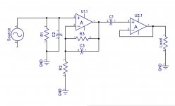
Amp (attachment 2 - amp.jpg x2):
- C1 = 2.2μF/250V Polypropylene
- C2/C3 = 220pF/50V Ceramic
- R1 = 5.1KΩ ½W metal film
- R2 = 6.8KΩ ½W metal film
- R3 = 20KΩ ½W metal film
- U1/U2 = Burr-Brown OPA2134PA
I've basically tried to set up a two-stage CMoy design with this, borrowing elements of the Objective2. Unfortuantely the only part of this that I'm sure of is that R2 and R3 give me a gain of just short of 4 - the rest I'm only speculating about.
My speculation is basically that R1 and C1, together, provide a HPF with a corner frequency just over 14Hz. C1, if I'm also understanding correctly, is to eliminate (or at least control) DC offset from the output. C2 and C3 are directly borrwed from the O² and other CMoy designs I've seen, and best I can figure they're for noise reduction as in the power circuit (I'll be honest in that I have no real idea what they're for).
Cascading the Op Amps was done for two reasons. First is that I figure using both Op Amps for both outputs means they'll be more even (though I suspect if they were one each than cross-talk would be reduced). Second is that I'm hoping the second Op Amp, with its 10 trillion ohm input impedence, will basically eliminate potential voltage shift on the virtual earth as described in Tangent's articles on why the CMoy is not good for low impedance loads.
The part of this that's not pictured, however, is the earth isolation. Since my power and signal share an earth, I cannot directly connect the signal earth to the virtual earth. My current amp gets around this with a "Ground Loop Isolator", which is essentially two AC-AC transformers (170Ω input, 100Ω output). I can repeat this, naturally, but I'm wondering if there's a better or simpler option.
-----
As you can see, I'm really not sure with this design. I'm fairly sure it will work, but I have my doubts that it will work as I expect - or even to the point where it's worth building. This isn't my field of expertise but I've become increasingly more curious over the past week or so building the CMoy I mentioned.
I should also say that the only reason I'm looking into this is because said CMoy has some constant noise in the output which has bested all of my efforts to correct it, so I'm hoping this will be a more solid design. What makes the noise more baffling is that it is completely inaudible (to me, anyway) through my Sennheiser PC 320s - but very audible through anything else.
Comments, critiques, thoughts and ideas welcome.
Having recently built myself a slightly modified CMoy amp, I've been curious to know if I can take that knowledge and make something better suited to my purposes. These purposes are as follows:
- Must operate from 5VDC or 12VDC (supply is a PC PSU, thus PWM)
- Must be sourced from local supplier (Jaycar)
- Must be relatively straight forward (MOSFETs are what now?)
- Must work with low impedance headphones (64Ω Sennheiser HD 280 Pro)
- Must sound "good enough"
That last one is perhaps the easiest. I have no CRO or other testing equipment - just a hand-held multimeter and my two ears, and one of those ears is for display purposes only. It doesn't have to test like the greatest thing ever built, nor reach un-Godly volumes, so long as it's enough all around.
Credit goes to Chu Moy, Tangent and NwAvMan. This design is based on my interpretation of the work of the three of them (the CMoy and Objective2). Since my field is more electrics (auto electrics if I'm honest) than electronics, I suspect I've gotten more than a few things wrong - hence this thread.
Power (attachment 1 - power.jpg):
- B1 = 5VDC (hopefully)
- C1/C2 = 220pF/50V Ceramic
- C3/C4 = 470μF/16V L/ESR Electrolytic
- R1/R2 = 220KΩ ½W metal film
- R3 = 1KΩ ½W metal film
- U1 = National Semiconductor LM741 (DipTrace decided it shouldn't be a triangle)
This is essentially the Op Amp stabilized virtual earth that Tangent described. I basically understand that the resistors work as a voltage divider and that the Op Amp should maintain that mid-point or die trying. If I'm right, it should be good for 25mA sustained output with peaks of 40mA (my current, single OPA2134PA CMoy barely reaches 12mA with my usage).
What I'm unsure of is whether C1/C2 will work as noise suppression for the PWM supply, or if an extra bypass cap is needed in the feedback loop. I'm also wondering if C3/C4 would be better off replaced by, or even supplimented by a single capacitor before the divider. I'm also unsure whether R3 is strictly necessary, the right value, or even if it will cause problems given how close I'm operating to the bare minimum power requirement of my Op Amps.
My main concern here is that noise will be introduced to the system as a result of the PWM, which is what I suspect is causing my problem with the CMoy I've already built.
Amp (attachment 2 - amp.jpg x2):
- C1 = 2.2μF/250V Polypropylene
- C2/C3 = 220pF/50V Ceramic
- R1 = 5.1KΩ ½W metal film
- R2 = 6.8KΩ ½W metal film
- R3 = 20KΩ ½W metal film
- U1/U2 = Burr-Brown OPA2134PA
I've basically tried to set up a two-stage CMoy design with this, borrowing elements of the Objective2. Unfortuantely the only part of this that I'm sure of is that R2 and R3 give me a gain of just short of 4 - the rest I'm only speculating about.
My speculation is basically that R1 and C1, together, provide a HPF with a corner frequency just over 14Hz. C1, if I'm also understanding correctly, is to eliminate (or at least control) DC offset from the output. C2 and C3 are directly borrwed from the O² and other CMoy designs I've seen, and best I can figure they're for noise reduction as in the power circuit (I'll be honest in that I have no real idea what they're for).
Cascading the Op Amps was done for two reasons. First is that I figure using both Op Amps for both outputs means they'll be more even (though I suspect if they were one each than cross-talk would be reduced). Second is that I'm hoping the second Op Amp, with its 10 trillion ohm input impedence, will basically eliminate potential voltage shift on the virtual earth as described in Tangent's articles on why the CMoy is not good for low impedance loads.
The part of this that's not pictured, however, is the earth isolation. Since my power and signal share an earth, I cannot directly connect the signal earth to the virtual earth. My current amp gets around this with a "Ground Loop Isolator", which is essentially two AC-AC transformers (170Ω input, 100Ω output). I can repeat this, naturally, but I'm wondering if there's a better or simpler option.
-----
As you can see, I'm really not sure with this design. I'm fairly sure it will work, but I have my doubts that it will work as I expect - or even to the point where it's worth building. This isn't my field of expertise but I've become increasingly more curious over the past week or so building the CMoy I mentioned.
I should also say that the only reason I'm looking into this is because said CMoy has some constant noise in the output which has bested all of my efforts to correct it, so I'm hoping this will be a more solid design. What makes the noise more baffling is that it is completely inaudible (to me, anyway) through my Sennheiser PC 320s - but very audible through anything else.
Comments, critiques, thoughts and ideas welcome.