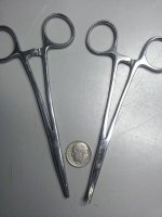
On the subject of soldering and tools, Andrew T recommended the concept of heatsinks on the leads when soldering a heat sensitive device. That sent me to the internet where I learned that some people think an alligator clip works just fine for this task. I also found these which are interesting because they are narrower than an alligator, aluminum (sorry Andrew, aluminium), and reasonably cheap.
heatsink_clip - My Photo Gallery
Soldering Heat Sink (2) | eBay
heatsink_clip - My Photo Gallery
Soldering Heat Sink (2) | eBay
To each his own, but I just don't think you have to go that far. Remember those SMD parts are installed in some pretty hot applications.
Again, the local CVS eyebrow section gave me a cheap solution for heat sinking.
Again, the local CVS eyebrow section gave me a cheap solution for heat sinking.
Attachments
Last edited:
I don't see nothin'
Bob,
I always go too far. For example, the magnifying glass wasn't good enough for me.
microscope - My Photo Gallery
Jac
To each his own, but I just don't think you have to go that far.
Bob,
I always go too far. For example, the magnifying glass wasn't good enough for me.
microscope - My Photo Gallery
Jac
Yea, It's amazing how we can talk ourselves into getting what we really want by by discovering a need based on another project. Works for me.")
Yea, I need a new DMM ! What brand do you suggest (considering my avatar) ?
I bought a Fluke more than 20 years ago and have never regretted it. That doesn't help with your avatar, however.
If you are going for it, you might consider getting one that measures capacitance too. SoiL4X4 just bought a AM-270 DMM. Maybe that will work for you. It looks like it can be had for less than $100.
Jac
If you are going for it, you might consider getting one that measures capacitance too. SoiL4X4 just bought a AM-270 DMM. Maybe that will work for you. It looks like it can be had for less than $100.
Jac
There are a million good choices. Even the sub $20.00 can be quite useful for what we do. This one has served me well and has capabilities far beyond my needs - so far. Home Depot puts it on sale often.
http://www.ryobitools.com/product_manual/file_url/469/RP4020_664_trilingual.pdf
I bought a set of mini hooks from Radio Shack that fit the probe point.
Mini Test Clip Adapters : Adapters | RadioShack.com
http://www.ryobitools.com/product_manual/file_url/469/RP4020_664_trilingual.pdf
I bought a set of mini hooks from Radio Shack that fit the probe point.
Mini Test Clip Adapters : Adapters | RadioShack.com
Last edited:
Yea, I need a new DMM ! What brand do you suggest (considering my avatar) ?
I'm using this one.
It's cheap but well built.
Last edited:
I have only played around with the amprobe AM-270 a little measuring the caps and a few resistors I have laying around, but so far I am really happy with this DMM. I built my other amp with a craftsman DMM and it did the job ok but the amprobe is definitely miles ahead. It was great to be able to choose a range and get a uf measurement without having to move the decimal. I found mine on amazon, it was about $90 shipped.
That was what I was trying to point out. But I am only a Jack of all trades, not even half as smart as lots of guys that are able to dig into the nitty gritty details.Boy, am I in over my head !
Thought it would be a fun challenge where I might learn something, but between the gerbbers, schematics and renderings, what I figured out was my need to do a whole lot more reading and study.
I did see what I think soongsc is refering to with R11. The blue path can't be completed because R11 performs "Groundes Interruptus". Correct?
Don't know if I'll ever have the time and brain power to catch up to you tech types.
Can't believe that just being away for two days there can be so much catching up to do.
Hey Mr. S,
I am still going to try to do as Andrew suggested when I find time just for fun and discovery in my learning path.
Also wanted to clear up what I said in post #1020. I will install sockets temporarily during the RC (release candidate PCB) build and test phase to accommodate any possible last minute changes in the BOM. I don't intend to leave them on the boards. I've been so surprised by the cap orientation tests that I want to keep that option open and easy for a while.
Last edited:
Hi guys,
I was able to do some measurements of the (shielded and grounded) FE proto on the AP rig.
Rload was 3.67R, Supply 18Vac toroid (+-24V rails), standard bridges, 4700uF. Speaker return at PGND (relay unused).
20R source resistance, no input cap (C13), floating drive (no leakage currents through R11).
A teaser here :
Red : 111Hz @250mVrms input (8Vrms/17W out)
Cyan : 4kHz @300mVrms input (9.6Vrms/25W out -- close to the maximum with the supplies I used)
Yellow : IMD 18.5kHz+19.5kHz (150mVin each)
Harmonic distortion is around -100dB (0.001%) with a nice monotonic decrease of higher orders.
At lower levels the HD quickly vanished in the noise floor.
IMD is better than -90dB.
Hum/buzz components with these signals are 110dB down (and effectively non-visible with no input signal).
A very respectable performance !
Attachments
Hi Klaus,
It means R11 shorted?
If so it would be interesting to know if with R11 populated results are different.
Fantastic!
Could I ask you to answer my last questions related to your previous post?
floating drive (no leakage currents through R11).
It means R11 shorted?
If so it would be interesting to know if with R11 populated results are different.
A very respectable performance !
Fantastic!
Could I ask you to answer my last questions related to your previous post?
So, if I've undestood correctly with 33VDC rails all seem to work as expected.
We could say that also with the 28VAC secondaries suggested for 4 Ohm loads the 27V zener is adequate?
You measured with C102/C202 in place?
Parts shortage
For those wanting to use the alternate compensation that part is quite out of stock (Mouser):
MC08EA270J-F (27pF 0805 SM)
Digikey has them.
Also MK132 200R are out of stock (Mouser, Digikey don't have them).
Both parts can be swapped with the 'on a budget' equivalent part.
For those wanting to use the alternate compensation that part is quite out of stock (Mouser):
MC08EA270J-F (27pF 0805 SM)
Digikey has them.
Also MK132 200R are out of stock (Mouser, Digikey don't have them).
Both parts can be swapped with the 'on a budget' equivalent part.
R11 was in place. Floating was referering to the AP's output (xfomer coupled), no current can establish in R11. And as I stated before, any current through it will cause a voltage (1V per ampere) and that voltage appears 1:1 at the output. It does NOT provide ground loop "isolation".It means R11 shorted?
If so it would be interesting to know if with R11 populated results are different.
For the other two questions, yes and yes.
It's effect will most probably not show up other than in increased hum if not well shielded. I have some Mundorf MCAP RXF and various WIMA that I might give a try, also using realistic source impedances (100R...1k).Since so many consider C13 a highly significant component, what do you suspect would be its effect on those readings/responses?
But if your source has no or little DC, say 30mV or less, I don't see any need to use that cap and no cap is the best cap. With balanced source impedance at the LM318's input pins (390Ohms, would required DC coupled source output) and using it's offset adjust capabilites there will probably be no need for C9 as well and the amp would be fully DC coupled. When using C9 it better should be a non-polar IMHO (two 'lytics back to back, or true non-polar with smooth foil).
Startup and powerdown noise is also very benign so the relay plus associated components might be discarded, too. That is, if you know what you're doing and you woofers can handle DC there is little risk of damage IMHO once the amp is properly built. Most errors happen during testing.
Less experienced builders/users and those who want to keep the amp universal should use the stock setup, though.
Last edited:
Thanks Bob, Allied has also the SM:
Cornell-Dubilier - MC08EA270J-F - Passive Components - Capacitors - Allied Electronics
For European builders RS components has the SM and the MK132:
2509275887
2509562807
Last edited:
- Status
- This old topic is closed. If you want to reopen this topic, contact a moderator using the "Report Post" button.
- Home
- Amplifiers
- Chip Amps
- My_Ref Fremen Edition - Beta build/Fine tuning