The transistors might still be fine, but when using both on 1x heatsink you are pushing +30-50V and -30-50V into each end of the heatsink, and when beginning to apply power from the TDA all you are doing is shorting the 2x transistors (with the resistance that an aluminium plate will provide)
First the 6.8Ohm is for sync and can't see you can get more efficiency or what ever you are trying to achieve......
I like your design. A WHOLE LOT! A powerful amp without biasing, and easy to build.
I just want to tweak it a bit to see if there is any room for improvement. And if not, then leave it as is.......
Your 6.8 ohms is fine. I want to go to 4.7 ohms sync (or less maybe) so the amp is driving the speaker a bit harder by itself directly before the voltage drop across the sync resistor turns on the output transistors to take over. It's just to reduce crossover distortion, because I'd like to drive 2 or 1 ohm and have full treble quality.
I've also considered adding 0.47 or 1 ohm resistors to the bases of the output transistors to have them turn-on a bit softer during SYNC to reduce any further distortion, at slight expense of voltage drop to improve linearity.
You don't hear the normal crossover distortion you get from driving too low ohm speaker anyway with your chip because the sync resistor adds resistance (less load) at lower signal levels, so you still get to enjoy the class AB biased linearity of the output stage inside the chip.
Also I want to use OTHER chip-amps for this same design. I have SEVERAL STK Video Amplifier Chips that look like good for this....All capable of over +/- 40V
Well just at the point where i was about to bridge 2 TDAs, I broke 2 pins of one,
Now what?
I find inmy parts boxes i have 2 pairs of sc5200 and sa1943 !!!
lucky lucky!
Now i have to try this way of yours...
Ill be testing tomorrow with the one that did not get broken.
Ill post pictures and tell you about how it sounds. thanks for your
comments.
Now what?
I find inmy parts boxes i have 2 pairs of sc5200 and sa1943 !!!
lucky lucky!
Now i have to try this way of yours...
Ill be testing tomorrow with the one that did not get broken.
Ill post pictures and tell you about how it sounds. thanks for your
comments.
Last edited:
hi
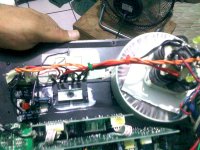
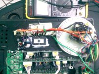
this is the final assembly, had to make a time to finish the amp section, later i´ll deal with thepre section, so far last ite itried it but had a bad insulation in teh chips tab, and it was sending 30 something volts at the output. Right now i just put a new insulating mica and washer and it´s OK as far as the DVM says. I´ll try it and post afterwards. thanks.
It is different ´cause i used Mr. Daniels W schem for the chip part and from there he rest is by yours, so o´ll try and see what i get
Attachments
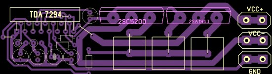
i think Mr. Andrewlebon pcb is missing input and output pads
yes just a quick pcb to check if schematic is ok i have tested amp on 2 ohms 4 15 inch speakers in parallel FULLY SATISFIED with performance of amp so i am designing stereo
pcb with 2 output pairs per channel so they can be bridged or used as stereo
warm regards
andrew lebon
yes just a quick pcb to check if schematic is ok i have tested amp on 2 ohms 4 15 inch speakers in parallel FULLY SATISFIED with performance of amp so i am designing stereo
pcb with 2 output pairs per channel so they can be bridged or used as stereo
warm regards
andrew lebon
well thats good! and by the way did not mention that your pcb looks very good to me, just noticed about those missing,and ; what power supply are you using?
mine is what is inthe pics, 25-0-25 ac xfrmer, single diode bridge, and 4x 4700uF, plus
2x 220uF at the chip as recomended by Mr Daniel W.Any plans for a final single transistor pair mono pcb?
mine is what is inthe pics, 25-0-25 ac xfrmer, single diode bridge, and 4x 4700uF, plus
2x 220uF at the chip as recomended by Mr Daniel W.Any plans for a final single transistor pair mono pcb?
EWorkshop1708:
Tweak away, if any improvements can be made that's good, i only got it working and spent 10 hours tweaking because im kind of a perfectionist, and would not post here if it did not work, lots of those designs out there, and this design (not mine by the way) i found some years ago, sounded awful and abandoned it, a year later i was looking again to build a new amp and decided to try this again to make a simple to build amp.
And yes no distortion no matter how much you mess up on the crossover components")
martin martinez:
Looking good, my first look more messy, the "newer" compact design helped alot on the tidiness.
andrewlebon;
Nice PCB and very glad you like the amp.
Don't know about the bridging, never had time to experiment more, have just been using this AMP non stop for 5 years or so.
------
Im sorry for the VERY late response but have been absolutely swamped in projects etc, my primary concern right now is to complete my Electro DM50, since the motor in the Electro CIAO is on it's last legs and don't want to use any time on it since it has served it's purpose as R&D for 3+ years to transfer to the new bike
Tweak away, if any improvements can be made that's good, i only got it working and spent 10 hours tweaking because im kind of a perfectionist, and would not post here if it did not work, lots of those designs out there, and this design (not mine by the way) i found some years ago, sounded awful and abandoned it, a year later i was looking again to build a new amp and decided to try this again to make a simple to build amp.
And yes no distortion no matter how much you mess up on the crossover components
martin martinez:
Looking good, my first look more messy, the "newer" compact design helped alot on the tidiness.
andrewlebon;
Nice PCB and very glad you like the amp.
Don't know about the bridging, never had time to experiment more, have just been using this AMP non stop for 5 years or so.
------
Im sorry for the VERY late response but have been absolutely swamped in projects etc, my primary concern right now is to complete my Electro DM50, since the motor in the Electro CIAO is on it's last legs and don't want to use any time on it since it has served it's purpose as R&D for 3+ years to transfer to the new bike
Hello Dr frost
greetings just made and tested 2 pair version can i bridge both channels
for 2 ohms load i would like to try the TDA7293 VERSION if its possible can you share schematic i have made d class h class AB class amps but i am in love with your splendid
amplifier many mant THANKS for sharing it
warm regards
andrew lebon
someone posted the bridge via feedback between to TDA's, i have only tested Bridge (along time ago) with the tried and tested method of inverted amplifier, like LEFT is LEFT and RIGHT is INVERTED RIGHT, i did this using cool-edit audio editor, loading a song and inverting RIGHT channel, putting subwoofer (1400W RMS capable) terminals "+"/"-" onto LEFT "+" and RIGHT "+", Both "-" are as you can see in the schematic GND, this is the same method that is used in almost all CAR-AMP's, they all have RIGHT channel inverted and "+"/"-" (output) switched around.
Here is the TDA7293 (i do believe i posted this before but this thread is becoming pretty long)
Very subtle difference from TDA7294 is PINS 12 & 14
Here is the TDA7293 (i do believe i posted this before but this thread is becoming pretty long)
An externally hosted image should be here but it was not working when we last tested it.
Very subtle difference from TDA7294 is PINS 12 & 14
![DSCN4850 [800x600].JPG](/community/data/attachments/326/326738-4a18836b62e00ee48a1686387911436f.jpg)
![DSCN4847 [800x600].JPG](/community/data/attachments/326/326743-7259ceec5dc728cdb85e2943adf4aee9.jpg)
andrewlebon now that really looks good , and can see your are opting for even more power using 2x Pairs, your amp should be stable in 2 OHM in bridge giving you one hell of alot of power
, and can see your are opting for even more power using 2x Pairs, your amp should be stable in 2 OHM in bridge giving you one hell of alot of power- Home
- Amplifiers
- Chip Amps
- TDA7294 + Power Transistors AMP (TDA7293 to come also)