Hi all!
I got two LM1875 chips in the mail today and I'm about to start building as soon as I can. I'm now here to flesh things out and I have a few questions!
I've been reading Peter Daniel's threads until my head hurts and intend to make the power supply somewhat similar to his GC's.
1. I'm planning to use one transformer. Does this 2x18 one look good? Is there any reason to go above 80VA?
2a. Using just one transformer it's possible to use either one or two diode bridges, right? Something like these:

Sorry about the image quality, I'm not used to drawing schematics with a specific software (although I've tried a bunch of different ones), it's much faster for me to draw it on paper and "scan" it with my phone.")
2b. I have a bunch of SB560 5A/40V diodes that I intend to use, the voltage might indicate it's better to split them over two separate bridges?
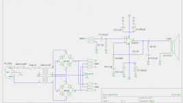
Here is a rough sketch of the whole thing based on the datasheet, with changes suggested in this thread:

3. I have some 50V 2200uF caps lying around so I'm probably going to use them first and then substitute them for 1000-1500uF low ESR caps (like Panasonic FC's) at a later point. Is this okay?
The layout will be pretty compact, keeping the wiring to a minimum, fwiw.
4a. About the decoupling caps, what are the drawbacks of not using small 0.1uF caps near the IC, which seems to be somewhat standard practice? I've left them out for now but can always put them in if needed.
4b. IIRC Peter Daniel has used 100uF caps instead, is it something I should experiment with?
5. Some designs have a larger NFB cap, is it beneficial to use something like 47uF instead of 22 and how will it affect things in the grand scheme?
And another thing.. I also read a thread where danielwritesbac wanted to create a high gain amp with a highpass filter in it. I've been thinking that might be a good thing as I intend to use the amp to drive small speakers (5" woofer) so I don't need low bass (and if I do I'll add a separate subwoofer). His final schematic looked like this (too lazy to find the thread right now):

5. These values are off the chart though, is there an easier way to make a simple (6db?) HP filter somewhere around 40hz and is it even a good idea?
I appreciate any and all answers/advice and I'm sure to have more questions later.
I got two LM1875 chips in the mail today and I'm about to start building as soon as I can. I'm now here to flesh things out and I have a few questions!
I've been reading Peter Daniel's threads until my head hurts and intend to make the power supply somewhat similar to his GC's.
1. I'm planning to use one transformer. Does this 2x18 one look good? Is there any reason to go above 80VA?
2a. Using just one transformer it's possible to use either one or two diode bridges, right? Something like these:
Sorry about the image quality, I'm not used to drawing schematics with a specific software (although I've tried a bunch of different ones), it's much faster for me to draw it on paper and "scan" it with my phone.
2b. I have a bunch of SB560 5A/40V diodes that I intend to use, the voltage might indicate it's better to split them over two separate bridges?
Here is a rough sketch of the whole thing based on the datasheet, with changes suggested in this thread:
3. I have some 50V 2200uF caps lying around so I'm probably going to use them first and then substitute them for 1000-1500uF low ESR caps (like Panasonic FC's) at a later point. Is this okay?
The layout will be pretty compact, keeping the wiring to a minimum, fwiw.
4a. About the decoupling caps, what are the drawbacks of not using small 0.1uF caps near the IC, which seems to be somewhat standard practice? I've left them out for now but can always put them in if needed.
4b. IIRC Peter Daniel has used 100uF caps instead, is it something I should experiment with?
5. Some designs have a larger NFB cap, is it beneficial to use something like 47uF instead of 22 and how will it affect things in the grand scheme?
And another thing.. I also read a thread where danielwritesbac wanted to create a high gain amp with a highpass filter in it. I've been thinking that might be a good thing as I intend to use the amp to drive small speakers (5" woofer) so I don't need low bass (and if I do I'll add a separate subwoofer). His final schematic looked like this (too lazy to find the thread right now):
5. These values are off the chart though, is there an easier way to make a simple (6db?) HP filter somewhere around 40hz and is it even a good idea?
I appreciate any and all answers/advice and I'm sure to have more questions later.
Yes, but 18 V is definitely too high for 4 Ohm speakers and scratching the limits even for 8 Ohm.1.Does this 2x18 one look good?
No.Is there any reason to go above 80VA?
Yes, but you got the lower rectifier in the two-rectifier version the wrong way round.2a. Using just one transformer it's possible to use either one or two diode bridges, right?
Diodes need a voltage rating of 4,25 times or more of the nominal transformer voltage. The AC peak to peak value is 2*sqrt(2)*Unom and you add 50 % tolerance on top of that to allow for regulation and mains fluctuation. For an 18 V transformer that is ~76,5 V, which calls for a rating of 80 V or more. Your 40 V rated diodes are only good for 9 V transformer voltage.2b. I have a bunch of SB560 5A/40V diodes that I intend to use, the voltage might indicate it's better to split them over two separate bridges?
2200 µF is better than 1000-1500 µF, so why change later on?3. I have some 50V 2200uF caps lying around so I'm probably going to use them first and then substitute them for 1000-1500uF low ESR caps (like Panasonic FC's) at a later point. Is this okay?
In extreme cases the lack of decoupling can lead to oscillation, in less extreme cases all disturbances on the rails will enter the amplifier through the supply pins and lead to noise and higher distortion.4a. About the decoupling caps, what are the drawbacks of not using small 0.1uF caps near the IC,
No.4b. IIRC Peter Daniel has used 100uF caps instead, is it something I should experiment with?
The smaller the cap, the higher is the LF roll-off. You must of course see this in conjunction with the input filter. The -3 dB point is at f = 1 / (2*PI*R*C), so 3,29 Hz for the input filter and 8,82 Hz for the NFB filter, which would sink to 4,13 Hz with 47 µF. Depending on the speakers you connect, this may or may not be audible. It depends on your taste, if you will like the lower roll-off with less phase-turns better or the more relaxed performance of the speakers for not having to deal unnecessarily with low frequencies that they may not be able to deal with.5. Some designs have a larger NFB cap, is it beneficial to use something like 47uF instead of 22 and how will it affect things in the grand scheme?
You already have two high-passes in your schematic. High gain is not necessarily better or worse, so the safe way is to stick with the datasheet application first.danielwritesbac wanted to create a high gain amp with a highpass filter in it. I've been thinking that might be a good thing as I intend to use the amp to drive small speakers (5" woofer) so I don't need low bass (and if I do I'll add a separate subwoofer). His final schematic looked like this (too lazy to find the thread right now):
Yes to all. You should however take into consideration that the two filters add up, so for a 40 Hz filter you may need something around 25 Hz at the input and another 25 Hz for the NFB. To maintain your resistor values you need to replace the 2,2 µF with 330 nF and 22 µF with 6,8 µF.v5. These values are off the chart though, is there an easier way to make a simple (6db?) HP filter somewhere around 40hz and is it even a good idea?
Yes, but 18 V is definitely too high for 4 Ohm speakers and scratching the limits even for 8 Ohm.
The datasheet says max. 60V, doesn't that mean +-30V DC? Are there graphs containing this information?
Yes, but you got the lower rectifier in the two-rectifier version the wrong way round.
Thanks for pointing that out!
Diodes need a voltage rating of 4,25 times or more of the nominal transformer voltage. The AC peak to peak value is 2*sqrt(2)*Unom and you add 50 % tolerance on top of that to allow for regulation and mains fluctuation. For an 18 V transformer that is ~76,5 V, which calls for a rating of 80 V or more. Your 40 V rated diodes are only good for 9 V transformer voltage.
That's unfortunate if true. So using two bridges doesn't make a difference (compared to a single one)?
Fwiw I've read a bunch of threads with people using SB560 claiming they sound good. Some of them:
http://www.diyaudio.com/forums/chip-amps/133259-can-lm3886-bpa300-beats-plinius-quality-4.html
http://www.diyaudio.com/forums/chip-amps/35889-pedjas-regulated-psu.html
http://www.diyaudio.com/forums/chip-amps/21256-whats-wrong-large-filter-caps-gainclone-14.html
Pedja acknowledges it here but he's speaking of 2x30V: http://www.diyaudio.com/forums/chip...ulated-buffered-inverted-gc-2.html#post412909
Here's Pedjas design w/ 24V secondaries: Building a Gainclone chip amp with a regulated power supply (PSU).
However I've read a bunch of your posts here on the forum and you seem highly knowledgeable and if you're certain it's a bad idea to use SB560's I'm just going to take your word for it and order some MUR860's.
2200 µF is better than 1000-1500 µF, so why change later on?
I'm not sure that the 2200 uF I have are low ESR, they're cheapish Vishay BC caps.
In extreme cases the lack of decoupling can lead to oscillation, in less extreme cases all disturbances on the rails will enter the amplifier through the supply pins and lead to noise and higher distortion.
Sounds like something I could experiment with then.
The smaller the cap, the higher is the LF roll-off. You must of course see this in conjunction with the input filter. The -3 dB point is at f = 1 / (2*PI*R*C), so 3,29 Hz for the input filter and 8,82 Hz for the NFB filter, which would sink to 4,13 Hz with 47 µF. Depending on the speakers you connect, this may or may not be audible. It depends on your taste, if you will like the lower roll-off with less phase-turns better or the more relaxed performance of the speakers for not having to deal unnecessarily with low frequencies that they may not be able to deal with.
Thanks for this information! I'm going to do some calcs.
And thanks for the whole answer, for taking the time to do it. Very informative!
Some additional questions.
How audible is phase-shifting at frequencies below 40 Hz? I would assume not that much and in that case the added benefits of the HPF are clear.
Should the two filters be somewhat balanced or can I just switch the 22 µF with 4.7 µF for 41.3 Hz? And, if I'm free to balance the filters as I like, is it better to put it on +in or -in?
Heh, I might install a cap switchboard in the amp to try out different combinations on the fly. In any case a switch for the HPF would be useful, for instance when testing the amp with other (lower freq. output) speakers.
The smaller the cap, the higher is the LF roll-off. You must of course see this in conjunction with the input filter. The -3 dB point is at f = 1 / (2*PI*R*C), so 3,29 Hz for the input filter and 8,82 Hz for the NFB filter, which would sink to 4,13 Hz with 47 µF. Depending on the speakers you connect, this may or may not be audible. It depends on your taste, if you will like the lower roll-off with less phase-turns better or the more relaxed performance of the speakers for not having to deal unnecessarily with low frequencies that they may not be able to deal with.
How audible is phase-shifting at frequencies below 40 Hz? I would assume not that much and in that case the added benefits of the HPF are clear.
You should however take into consideration that the two filters add up, so for a 40 Hz filter you may need something around 25 Hz at the input and another 25 Hz for the NFB. To maintain your resistor values you need to replace the 2,2 µF with 330 nF and 22 µF with 6,8 µF.
Should the two filters be somewhat balanced or can I just switch the 22 µF with 4.7 µF for 41.3 Hz? And, if I'm free to balance the filters as I like, is it better to put it on +in or -in?
Heh, I might install a cap switchboard in the amp to try out different combinations on the fly.
In any case a switch for the HPF would be useful, for instance when testing the amp with other (lower freq. output) speakers.That is one part of the story. The other is heat dissipation. The graphs contain this information. The power dissipation graph for 4 Ohm load shows two lines that are unluckily marked with * and **, while the corresponding comments are called Note 3 and Note 4, and that is also based on an ambient temperature of 25 °C.The datasheet says max. 60V, doesn't that mean +-30V DC? Are there graphs containing this information?
Yes, it does. For a single bridge you need double the voltage rating, because the rms voltage for the rectifier is 36 V, which makes the peak to peak voltage 102 V, and the voltage rating should be 160 V or higher then.That's unfortunate if true. So using two bridges doesn't make a difference (compared to a single one)?
One thing is good sound, if diodes really make a difference. The other is voltage rating. They were obviously just lucky that they haven't blown yet.Fwiw I've read a bunch of threads with people using SB560 claiming they sound good.
Bigger caps have lower ESR then smaller ones, so it is possible that a standard 2200 µF has the same ESR as a low-ESR 1000 µF cap. Low ESR is also not a necessity, if you stick to the common practice to use smaller caps next to the amp.I'm not sure that the 2200 uF I have are low ESR, they're cheapish Vishay BC caps.
Only, if you have a scope. If you haven't, put them in by all means.Sounds like something I could experiment with then.
That is one prize question. Or rather, how do you like the audible difference? Many here strife for the lowest possible crossing frequency to achive flat phase and frequency respsonse, because they assume any deviation is from flat is bad. That leads to DC coupled amps and DC servos. Others don't care. Interestingly the ones who don't care often work with PA equipment.How audible is phase-shifting at frequencies below 40 Hz? I would assume not that much and in that case the added benefits of the HPF are clear.
Another prize question. In the olden times the -3 dB point would be set with the NFB filter and the input filter would be chosen for a frequency sqrt(3) below that to achive a flat roll-off, because the NFB filter is a shelving filter and the input filter would set in, where the NFB filter starts to go flat again.Should the two filters be somewhat balanced or can I just switch the 22 µF with 4.7 µF for 41.3 Hz? And, if I'm free to balance the filters as I like, is it better to put it on +in or -in?
Nowadays there is a book by D.Self, where he states that the NFB filter must have a lower corner frequency to avoid distortion caused by too high voltage across the (electrolytic) NFB capacitor, which has led to religious beliefs for some people.
You could be faced with terrible switching noises as you switch capacitors on the fly. I recommend to switch the amp off before switching caps.Heh, I might install a cap switchboard in the amp to try out different combinations on the fly.
That is one part of the story. The other is heat dissipation. The graphs contain this information. The power dissipation graph for 4 Ohm load shows two lines that are unluckily marked with * and **, while the corresponding comments are called Note 3 and Note 4, and that is also based on an ambient temperature of 25 °C.
"Infinite heat sink". That sounds pretty funny in a sense. Not that I claim to have understood what the graphs mean even if I had studied them thorougly.
In any case I'm personally not too concerned as I'm not planning on having any rave parties at my house in the near future. Modest listening levels coupled with 8 ohm speakers (impedance curves of the speakers hardly over 7 ohm) and I should be fine.
Yes, it does. For a single bridge you need double the voltage rating, because the rms voltage for the rectifier is 36 V, which makes the peak to peak voltage 102 V, and the voltage rating should be 160 V or higher then.
That's what I figured. Ordered some MUR860's to be on the safe side.
Bigger caps have lower ESR then smaller ones, so it is possible that a standard 2200 µF has the same ESR as a low-ESR 1000 µF cap. Low ESR is also not a necessity, if you stick to the common practice to use smaller caps next to the amp.
I've come to the conclusion to use 0.1 µF caps with the larger ones.
Only, if you have a scope. If you haven't, put them in by all means.
Don't have one and they seem to cost more than an amp or two so... I'll leave out the scope for now and put in the caps for now.
Many here strife for the lowest possible crossing frequency to achive flat phase and frequency respsonse, because they assume any deviation is from flat is bad. That leads to DC coupled amps and DC servos. Others don't care. Interestingly the ones who don't care often work with PA equipment.
I was just talking to my brother who is a sound engineer and he was leaning towards the side that didn't care, lol. I'm still undecided.
In the olden times the -3 dB point would be set with the NFB filter and the input filter would be chosen for a frequency sqrt(3) below that to achive a flat roll-off, because the NFB filter is a shelving filter and the input filter would set in, where the NFB filter starts to go flat again.
I assume by "shelving filter" you mean a "baffle step"? Seems to fit the description and makes sense.
Nowadays there is a book by D.Self, where he states that the NFB filter must have a lower corner frequency to avoid distortion caused by too high voltage across the (electrolytic) NFB capacitor, which has led to religious beliefs for some people.
There are seemingly a lot of religious beliefs among audio enthusiasts.. The task of filtering out the relevant information can sometimes be daunting, especially for someone like me just starting out trying to understand it all.
If the NFB is a "baffle step", shouldn't we try to put its filtering freq close to the overall wanted frequency, like 40 Hz, and then adjust the input filter to cut off the "lower shelf"? This would go against Mr. Self's statement though as far as I can interpret it (unless the "corner frequency" is the point where the baffle starts to level out).
You could be faced with terrible switching noises as you switch capacitors on the fly. I recommend to switch the amp off before switching caps.
Will definitely do this if I decide to implement testing switches.
Speaking about testing switches, this will be my first amp "built from scratch" and I intend to experiment a bunch with it, so all kinds of testing switches might be used. My next amp will hopefully be built on a better foundation and be more sophisticated.
In the olden times the -3 dB point would be set with the NFB filter and the input filter would be chosen for a frequency sqrt(3) below that to achive a flat roll-off, because the NFB filter is a shelving filter and the input filter would set in, where the NFB filter starts to go flat again.
Hmmm, let me see if I understand this correctly.. If we chose the NFB filter freq as you say to 40 Hz, sqrt(3) of 40 would be 3.42 so it would work out pretty well overall with a 2.2 µF cap (as 2.115 µF would be required for this) at the input?
Sorry if I'm making you pick up your calculator too much over my basic schematic but this is interesting stuff, thanks again for all the detailed answers!
My old design in your first post has some flaws.
The testing voltage is not an appropriate operating voltage except if a current drop arrangement is installed, such as PI filter overdo, etc. . . and really not even then for 29v rails. Try to keep her down less than 28v rails. Install added filtering if necessary. That amplifier today runs with 27vdc rails.
The 22uF NFB cap is an incredibly borderline value, although that might work with a non-electrolytic cap. Without a massive hunt for the perfect little cap, I'm sure you'd appreciate a great deal larger value cap there, such as more than 200uF. Big enough is great, and a lot easier.
That amplifier today still has its miniature non-electrolytic 22uF cap. But, newer copies have much larger electrolytic caps.
That gain is slightly into the noise range. Either change the 2.2k to 2.7k or pull that 115k down to 100k. Anyway, it shows slightly too much gain, really right on the verge of tolerance. That needs better tolerance--a bit less gain. Today, that amplifier has 2.7k instead of the 2.2k shown.
The amp has remained in active service since built. Newer copies have had a rail to rail cap of 4.7uF 250v added for a more laid back sound. It tolerates a 4 ohm speaker with a 1st order parallel crossover (due to a lot of inductor loss) or a regular 6 ohm speaker. However, it uses heat spreader technique. If using a simple pad or mica, reduce load to an 8 ohm speaker.
Consider also the merits of a single rail amp, since the tab would then be ground, in the case of a single rail amp.
and. . .
That gainclone design posted earlier, with 27k/820R gain setting, is suffering a bit. The input load fails to show 20k pot's load paralleled directly onto that 22k resistor for about 11k input load. It also fails to show the 4.7uF input cap positioned between pot and rca jack. The only reason to use that 27k/820R with ~10k input load combination is zero dc offset despite omission of the NFB cap. Omitting the NFB cap has some caveats, and reduced dynamics, shorter lifespan (or needing lower voltage, lighter load) as well as having to add a third party speaker protector (just in case) are some of the caveats of NFB cap omission. That amp today has an output cap serving as an inexpensive speaker protector, although the velleman kit could be used. Or, you could use an NFB cap like 22uF//470uF, also paralleled with a tiny value polyester cap.
The output zobel with 1R infers using a very lossy cap of the same type found on the output of the original T-amp; however, if a non-lossy cap were used, that resistor value would change to about 5R.
Last edited:
The baffle step is an unwanted effect produced by the baffle of a speaker. The NFB filter response looks like a baffle step, but it is neither unwanted nor produced by a baffle.If the NFB is a "baffle step",
That is the idea that was used earlier. The input filter was chosen sqrt(3) = 1,73 times below the NFB filter as a compromise or maybe it was just low enough to not reduce the -3 dB point any further. If you try to cut the shelf in a way that results in a really straight roll-off, you would probably have to go 25 to 30 times below the NFB filter frequency.shouldn't we try to put its filtering freq close to the overall wanted frequency, like 40 Hz, and then adjust the input filter to cut off the "lower shelf"?
It would. The corner frequency is where the output has fallen to -3 dB, which means that the power output at that frequency is halved.This would go against Mr. Self's statement though as far as I can interpret it (unless the "corner frequency" is the point where the baffle starts to level out).
Sqrt(3) is the square root of 3, which is 1,73. For 40 Hz NFB you would need an input filter at or below 40/1,73 = 23 Hz and the cap for a 22 k input resistor would be 330 nF. The NFB cap for the typical 1 k resistor would be 3,9 µF As you can see you would save a lot of money on caps by choosing such a high roll-off frequency. You could even afford a film cap in the NFB loop.Hmmm, let me see if I understand this correctly.. If we chose the NFB filter freq as you say to 40 Hz, sqrt(3) of 40 would be 3.42 so it would work out pretty well overall with a 2.2 µF cap (as 2.115 µF would be required for this) at the input?
. . . For 40 Hz NFB you would need an input filter at or below 40/1,73 = 23 Hz and the cap for a 22 k input resistor would be 330 nF. The NFB cap for the typical 1 k resistor would be 3,9 µF As you can see you would save a lot of money on caps by choosing such a high roll-off frequency. You could even afford a film cap in the NFB loop.
True enough, the discontinued Panasonic epoxy caps do as you say.
Unfortunately, for practical application of electrolytic capacitors, you will need to multiply those particular cap examples by ten, as in 3.3uF input, ~390uF NFB.
For practical parts, one possible option could be could be 3.3uF Elna New Cerafine (or 2.2uF Nichicon ES) //10nF polyester dip cap for input and 330uF Elite PS//22uF Nichicon KZ//1nF polyster dip (non box) cap for NFB. This was the closest approximation that I could think up at the moment. It will work although I was excessive in using signal grade electrolytic, which will probably all have individual postage expense, since they are not commonplace.
Probably, the expense for film caps is not different. However, the different impedance being lesser in the film caps will make a harder sound in some circuits. And, probably the fix for that *difference* is a tiny value carbon resistor of minimal expense.
The other difference is frequency response, one like a tall wall, the other like a gentle hill.
I wonder if you can find compact, very low voltage, film caps to use for NFB caps?
That 115k/2.7k gain setting in the old highly dynamic AC coupled design was originally set up to use non-electrolytic caps for NFB cap. The original that is still in service is made this way. About 33uF should do decently. As a 16v film cap, that might be very small.
You'd still need to "trim" just a bit with the input cap, but the prospect is very helpful to small scale amplifiers for efficiency, and especially in combination with modest size speakers since those don't require a great deal of pitches lower than they can output. If the speaker size is working out for you, this sort of efficiency tuning can have the little 25 watt amplifier doing the job of a 50 watt amplifier. And that's kinda cool.
P.S.
It is possible or even probable that LM1875's low gain sister, the LM675 can do a really similar performance at a much lower gain setting.
And if that wasn't the case, then the LM675 could make really entertaining miniature howland current pump.
Last edited:
For 40 Hz NFB you would need an input filter at or below 40/1,73 = 23 Hz and the cap for a 22 k input resistor would be 330 nF. The NFB cap for the typical 1 k resistor would be 3,9 µF As you can see you would save a lot of money on caps by choosing such a high roll-off frequency. You could even afford a film cap in the NFB loop.
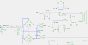
I've revised the schematic below. The 3.9 µF cap you suggested would filter at ~40 Hz with a 1k resistor so I changed it to a more standard size of 4.7 µF to go with the 820R resistor. I plan to use film caps on both input and NFB. How does the schematic look overall?
I haven't included a pot here as I'm toying around with the idea of building an external preamp (based on PGA2311 controlled by an Arduino) to go with it. Should I still leave a pot there to prevent potentially dangerous full volume accidents and if so, how do I calculate appropriate pot values in general? And also, if I use a preamp, is the slightly higher gain harmful or is it fine to leave it as it is, considering it would then also work as a standalone unit without the preamp (I would prefer to have this option)?
Attachments
Thinking only about the secondary AC current and the smoothing capacitors:
Trace out the route that the transformer charges up the smoothing capacitor when current flows from tapping 8 to the amp PCB and back to tapping 7. Do the same for charging current route t6 to t5.
Now reverse the AC current flow and trace out the route for charging current from Tapping 7 back to t8 and for t5 to t6.
Do any of those charging currents pass into the PCB traces or amplifier components?
Do any of those routes include a loop area that is significantly bigger than 10 sq mm?
Swap D5 to D8 around.
Last edited:
Specialty Piccolo amplifier???
C6 has the decimal point in the wrong place and will inspire an excellent quality conniption fit with no generally useful audio output, except as a "tweeter amp". For a film cap with very rare performance parameters, C6 could be 47uF if you wanted a bare minimum value with no conceivable reason to do so.
For an electrolytic solution, move the decimal point yet again because electrolytic has a response like gentle hill and you want the very top of that hill, not the bottom. A bare minimum example is like 0.5uF Nichicon ES//470uF Panasonic FC, although perhaps using these highest efficiency electrolytic could allow a smaller value. I'm not smart enough to know that; however I know for sure that 3,300 big low impedance power cap will easily beat the performance of 4.7uF for the NFB cap, since only one of those choices is able for audio. The point is "whatever is big enough and also clear."
Real time booster:
For a combination solution, we could use a "disadvantaged electrolytic" weakened to lose a fight with a film cap, in this way: Put 3.3R 1/2w carbon film resistor series to the groundside pin of a large value good performing electrolytic (470uF), and of course the opposite pin of that electrolytic cap connects to your 820R feedback-shunt resistor, and that point must physically touch the pin of C6 to cause the fight. Of course the free end of the 3.3R resistor connects to the ground of C6.
The lossy booster unit is now NOT able to overcome your high efficiency film cap at C6. But, when it is time for low bass, the added assembly will really pipe up, due to the absence of a more efficient competitor (condition occurs when C6 passes no audio). My favorite amplifier has this method. It is the band-aid patch for an amplifier that you love except for its bass performance being the only thing you want to change.
When the output end of two capacitors touch, yet the input side has different signal, the more efficient capacitor wins the war while the other is nearly silent. CapDiv, it is. There are many uses for that. If done on accident, results are terrible, but if done on purpose, it can be amazing.
You know all those amplifiers that have overly warm, nearly boomy bass with the annoying absence of really low notes? Well, here's the instant fix. I'm still baffled as to why one would want to cause the problem to begin with, but at least the fix is easy. Enjoy!
C6 has the decimal point in the wrong place and will inspire an excellent quality conniption fit with no generally useful audio output, except as a "tweeter amp". For a film cap with very rare performance parameters, C6 could be 47uF if you wanted a bare minimum value with no conceivable reason to do so.
For an electrolytic solution, move the decimal point yet again because electrolytic has a response like gentle hill and you want the very top of that hill, not the bottom. A bare minimum example is like 0.5uF Nichicon ES//470uF Panasonic FC, although perhaps using these highest efficiency electrolytic could allow a smaller value. I'm not smart enough to know that; however I know for sure that 3,300 big low impedance power cap will easily beat the performance of 4.7uF for the NFB cap, since only one of those choices is able for audio. The point is "whatever is big enough and also clear."
Real time booster:
For a combination solution, we could use a "disadvantaged electrolytic" weakened to lose a fight with a film cap, in this way: Put 3.3R 1/2w carbon film resistor series to the groundside pin of a large value good performing electrolytic (470uF), and of course the opposite pin of that electrolytic cap connects to your 820R feedback-shunt resistor, and that point must physically touch the pin of C6 to cause the fight. Of course the free end of the 3.3R resistor connects to the ground of C6.
The lossy booster unit is now NOT able to overcome your high efficiency film cap at C6. But, when it is time for low bass, the added assembly will really pipe up, due to the absence of a more efficient competitor (condition occurs when C6 passes no audio). My favorite amplifier has this method. It is the band-aid patch for an amplifier that you love except for its bass performance being the only thing you want to change.
When the output end of two capacitors touch, yet the input side has different signal, the more efficient capacitor wins the war while the other is nearly silent. CapDiv, it is. There are many uses for that. If done on accident, results are terrible, but if done on purpose, it can be amazing.
You know all those amplifiers that have overly warm, nearly boomy bass with the annoying absence of really low notes? Well, here's the instant fix. I'm still baffled as to why one would want to cause the problem to begin with, but at least the fix is easy.
Enjoy!
Last edited:
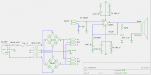
Man, you shouldn't have given away the answer, especially after providing a great way to realize my mistake! I did walk through the current flow (trying to forget your answer) as per your instructions and arrived at the same solution. Thanks in any case.
edit: image messed up
edit: image messed up
Attachments
Last edited:
Add a resistor between the input pins. A value between 100k and 1meg will help against popping noises.I've revised the schematic below. The 3.9 µF cap you suggested would filter at ~40 Hz with a 1k resistor so I changed it to a more standard size of 4.7 µF to go with the 820R resistor. I plan to use film caps on both input and NFB. How does the schematic look overall?
Add an X or Y rated capacitor between transformer pins 1 and 4. A few nF will do. Add 100 nF ceramic capacitors between transformer pins 5 and 6, 7 and 8 and between rectifier pins 3 and 4.
Would that really help?Should I still leave a pot there to prevent potentially dangerous full volume accidents
That is more a question of assessment. Higher values are easier to drive for the source, but add more Johnson noise. For volume pots a higher value means lower roll-off frequencies for the source's output filters. Practical values are 10k to 100k log.how do I calculate appropriate pot values in general?
Only in case of 'full volume accidents'.And also, if I use a preamp, is the slightly higher gain harmful
C6 has the decimal point in the wrong place and will inspire an excellent quality conniption fit with no generally useful audio output, except as a "tweeter amp". For a film cap with very rare performance parameters, C6 could be 47uF if you wanted a bare minimum value with no conceivable reason to do so.
Hmm according to the formula provided by pacificblue a 47 µF cap would filter -3db at ~4.13 Hz. Is this right or not?
- Status
- This old topic is closed. If you want to reopen this topic, contact a moderator using the "Report Post" button.
- Home
- Amplifiers
- Chip Amps
- Designing a LM1875-based amp