Hey, All.....
I typically hang out in the "Class A" Nelson Pass forums, but I could not resist putting together a Chip Amp based on the LM3886. Unfortunately, you'll see some of my Class A upbringing in my design, but I still hope this thread provides some useful info for new constructors.
I started off (fortunately, or otherwise....) with some left-over heatsinks and a toroid transformer from my lass Class A MOSFET project, and decided to use them in my Chip Amp design. (Yeah, the heatsink was probably overkill, but I had it handy!)
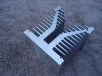
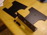
Here goes..... the heatsink was from Machtron, Inc, and purchased via eBay. It's a MASSIVE hunk of aluminum extrusion, and I elected to use one, split down the middle, to make two heatsinks for this project. (Even so, they run at ambient room temp, even after several hours of use....)
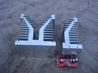
The pics attached show the original Machtron heatsink (unmolested), and then the half that was cut (on a metal bandsaw), trued up (on a milling machine) and then tapped for the LM3886.
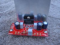
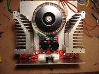
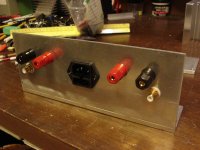
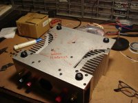
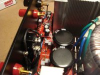
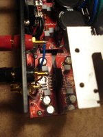
The next series of pics show the chassis fabrication and integration of the amp components. The chassis baseplate is 3/16" aluminum, while the rear apron is 1/8" aluminum (T06061 alloy was used). I welded the apron to the baseplate, to avoid using angle brackets and additional hardware. Another pic shows the layout of the rear apron. Despite the size of the heatsinks and toroid, I wanted to give the amp a small footprint--about 9" x 9"--so the chassis and apron layout are pretty compact..... this made for some fun wiring challenges. Final assembly was more like building a watch, than assembling an amp. The PCBs and components are from ChipAmp. Stuffing the amp boards and PSU presented no challenges--as always, read the assembly instructions (and the manufacturer's tech sheets!) to help fabrication. (Trust me, on this last point!)
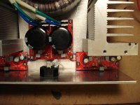
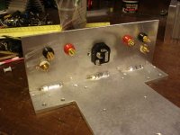
Since I had welded the rear apron to the baseplate, I used an old fabricators trick during wiring. I inverted the chassis, and since the design layout had "left-to-right" symmetry, I built the amp on the bottom side of the baseplace, effectively using the baseplate as an assembly jig (see pic). This helped me in routing wires and dressing lead length. If you notice, I ran most of the PCB interconnections UNDER the PCBs, to further clean up the assembly. Important, too, to consider routing for the AC and audio inputs (and outputs) in a build like this.
Pics also show the bottom of the baseplate (and the fasteners for the heatsinks, PCBs, etc.....and also the top of the coverplate (which is also 1/8" aluminum). The thickness of the chassis plates is probably also a hold-over from my Class A fabrication, but they certainly make a strong chassis!
I typically hang out in the "Class A" Nelson Pass forums, but I could not resist putting together a Chip Amp based on the LM3886. Unfortunately, you'll see some of my Class A upbringing in my design, but I still hope this thread provides some useful info for new constructors.
I started off (fortunately, or otherwise....) with some left-over heatsinks and a toroid transformer from my lass Class A MOSFET project, and decided to use them in my Chip Amp design. (Yeah, the heatsink was probably overkill, but I had it handy!)
Here goes..... the heatsink was from Machtron, Inc, and purchased via eBay. It's a MASSIVE hunk of aluminum extrusion, and I elected to use one, split down the middle, to make two heatsinks for this project. (Even so, they run at ambient room temp, even after several hours of use....)
The pics attached show the original Machtron heatsink (unmolested), and then the half that was cut (on a metal bandsaw), trued up (on a milling machine) and then tapped for the LM3886.
The next series of pics show the chassis fabrication and integration of the amp components. The chassis baseplate is 3/16" aluminum, while the rear apron is 1/8" aluminum (T06061 alloy was used). I welded the apron to the baseplate, to avoid using angle brackets and additional hardware. Another pic shows the layout of the rear apron. Despite the size of the heatsinks and toroid, I wanted to give the amp a small footprint--about 9" x 9"--so the chassis and apron layout are pretty compact..... this made for some fun wiring challenges. Final assembly was more like building a watch, than assembling an amp. The PCBs and components are from ChipAmp. Stuffing the amp boards and PSU presented no challenges--as always, read the assembly instructions (and the manufacturer's tech sheets!) to help fabrication. (Trust me, on this last point!)
Since I had welded the rear apron to the baseplate, I used an old fabricators trick during wiring. I inverted the chassis, and since the design layout had "left-to-right" symmetry, I built the amp on the bottom side of the baseplace, effectively using the baseplate as an assembly jig (see pic). This helped me in routing wires and dressing lead length. If you notice, I ran most of the PCB interconnections UNDER the PCBs, to further clean up the assembly. Important, too, to consider routing for the AC and audio inputs (and outputs) in a build like this.
Pics also show the bottom of the baseplate (and the fasteners for the heatsinks, PCBs, etc.....and also the top of the coverplate (which is also 1/8" aluminum). The thickness of the chassis plates is probably also a hold-over from my Class A fabrication, but they certainly make a strong chassis!
Attachments
-
 Chip1.JPG88 KB · Views: 1,710
 -
 Chip4.JPG87.8 KB · Views: 1,640
 -
 Chip8.JPG72 KB · Views: 1,637
 -
 Chip14.JPG57.5 KB · Views: 744
 -
 Chip13.JPG69 KB · Views: 785
 -
 Chip11.JPG60.1 KB · Views: 545
 -
 Chip18.JPG52.8 KB · Views: 1,578
 -
 Chip19.JPG50.6 KB · Views: 1,621
 -
 Chip20.JPG63.1 KB · Views: 623
 -
 Chip21.JPG58.9 KB · Views: 636
Last edited:
Part Deux....if you aren't bored yet....!
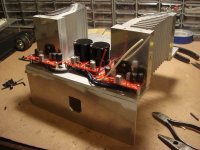
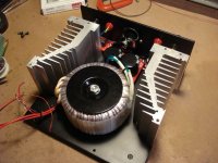
After test assembly I broke everything down, for final fabrication. (I must have had the heatsinks attached/removed from the baseplate at least a dozen times during contruction to check clearances, etc.) I should mention that the heatsinks were tapped in multiple places with 8-32 taps, and that the heatsinks effectively serve as the side structure of the chassis, sandwiched between the top and bottom aluminum plates. Both top and bottom plates were machined to permit maximum convective airflow for the heatsinks (which, again, was probably overkill....!)
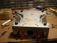
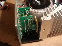
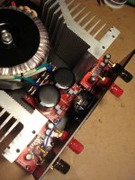
The next pics show the chassis after return from the powder-coater. I use a 10% matte black on my chassis, and I think it's worth the cost (about $30 for this chassis). Also shown are pics of the final wiring. The amp modules were designed to fit tightly between the rear chassis apron and heatsinks, and to minimize input audio and output audio lead lengths. I also routed the AC mains circuilts along the centerline of the chassis, and under the PSU PCB, to keep the AC lines as far as possible from the audio routes.
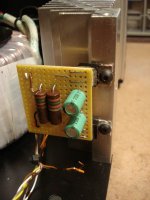
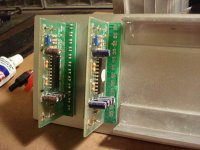
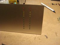
I also decided to add LED VU level meters for each channel. The VU PCBs were attained from an eBay supplier, and modified for use in this amp. The front panel was attained from Front Panel Express, and was machined to accept the left and right channel LEDs. Since my amp PSU rails are +/- 28 VDC, and the LED PCBs require 12-14 VDC, I added a small circuit board with dropping resistors and 12 VDC regulators to provide power for the VU displays. The VU PCBs and regulator board fit tightly in the forward right-hand side of the chassis, and I was able to use the right-hand heatsink as a mounting point for the two12 VDC regulators (although they run only slightly warm to the touch).
Details are contained in the pics.
After test assembly I broke everything down, for final fabrication. (I must have had the heatsinks attached/removed from the baseplate at least a dozen times during contruction to check clearances, etc.) I should mention that the heatsinks were tapped in multiple places with 8-32 taps, and that the heatsinks effectively serve as the side structure of the chassis, sandwiched between the top and bottom aluminum plates. Both top and bottom plates were machined to permit maximum convective airflow for the heatsinks (which, again, was probably overkill....!)
The next pics show the chassis after return from the powder-coater. I use a 10% matte black on my chassis, and I think it's worth the cost (about $30 for this chassis). Also shown are pics of the final wiring. The amp modules were designed to fit tightly between the rear chassis apron and heatsinks, and to minimize input audio and output audio lead lengths. I also routed the AC mains circuilts along the centerline of the chassis, and under the PSU PCB, to keep the AC lines as far as possible from the audio routes.
I also decided to add LED VU level meters for each channel. The VU PCBs were attained from an eBay supplier, and modified for use in this amp. The front panel was attained from Front Panel Express, and was machined to accept the left and right channel LEDs. Since my amp PSU rails are +/- 28 VDC, and the LED PCBs require 12-14 VDC, I added a small circuit board with dropping resistors and 12 VDC regulators to provide power for the VU displays. The VU PCBs and regulator board fit tightly in the forward right-hand side of the chassis, and I was able to use the right-hand heatsink as a mounting point for the two12 VDC regulators (although they run only slightly warm to the touch).
Details are contained in the pics.
Attachments
Last edited:
And, fini......!
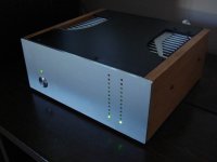
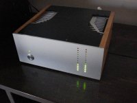
Pics of the final amp, in operation.....
Again, construction was straight-forward. The use of a "tight" chassis design made the fabrication a little challenging, but that was part of the fun.
The wooden side panels on the amp are solid 1/2" maple, finished with a mix of cherry-dark walnut oil stain.
The LED VU indicators have been calibrated, with the first "red" LED indicating the clipping level (determined with my audio signal generator and scope).
The amp sounds great. I'd recommend the LM3886 for an easy build, with good sound and ample volume levels into efficient speakers. This was a fun diversion from building Class A "room heaters"....
I hope my construction tips might help some of you'all out there.....
Ken
Attachments
Nice work, I will be following along.
I am also going to build an aluminum chassis. The welding is a good idea.
I wish I had a band saw. Normally I would cut the 1/4" stuff with a skillsaw and clean up the edges with a file, except one of my pieces is around 3/4". lol
I've had access to a HUGE metal brake, which has let me do "straight cuts" that are true and accurate. The curved stuff (like the cut-outs for the heatsink vents) were done on a bandsaw--and the curve of those cuts was a little challenge...... LOTs of filing, afterwards.....! That's one of the nice things about a "flat" powder coat finish--it can hide a lot of "minor sins" in metal fabrication.....!!
Good luck with your project--sounds like fun....!
Wonderful! Simply wonderful! The chassis is fantastic, and your love affair with VU meters gets yet another fix! ")
Send the photos to the chipamp.com website, I'm sure they will highlight it on their site!
Now I really want to finish mine... It's next after a phono stage.
(And then it's back to our regularly scheduled class-A room heaters!)
Send the photos to the chipamp.com website, I'm sure they will highlight it on their site!
Now I really want to finish mine... It's next after a phono stage.
(And then it's back to our regularly scheduled class-A room heaters!)
Heatsinks.....
Yep, these Machtron heatsinks are things of beauty....
I'm now dreaming up other (class A) projects, just so I can use more of them...!
Unfortunately, Jim--I have an unused pair I can show you, but I have them packed up already for the pending move to the Florida homestead (and I don't know which of the 50+ cartons have them....!)
But come on down, and look at my Chip Amp in person.....any time!
Ken
Normally, my first comment on chipamp builds is "Have you thought about the dissipation in the heatsinks?".
Rats!
Cracking build!
Thanks....! ....and the heatsinks are sooooo big, I can also use them to chill my red wines......!!!
I saw this thread referenced in another LM3886 build thread so had to have a look. Wonderful job and looks stunning! I'm getting ready to start an LM4702 based chip-amp project. I'm using some pre-assembled modules, but the case and layout will be of my design. It will be based on this amp module. It's been years since I tackled anything this major, but figured I have some time on my hands now so why not.
I can't fabricate my own case as you have so competently done, so am looking for off the shelf enclosures. I've looked at a few brands online that are nice looking, but since I haven't finished the final design I'm not sure on the exact size I need. I'm still waiting on most of the parts to show up. The project may go from an amp build to an integrated amp build, so additional space will need to be considered. Plus I have a monster toroidal to deal with. Do you have any recommendations for quality enclosures?
Anyway, just wanted to say thanks for sharing your amp design and build. I'm sure I can learn from your experience. Came out looking very professional and expensive!
I can't fabricate my own case as you have so competently done, so am looking for off the shelf enclosures. I've looked at a few brands online that are nice looking, but since I haven't finished the final design I'm not sure on the exact size I need. I'm still waiting on most of the parts to show up. The project may go from an amp build to an integrated amp build, so additional space will need to be considered. Plus I have a monster toroidal to deal with.
Do you have any recommendations for quality enclosures?Anyway, just wanted to say thanks for sharing your amp design and build. I'm sure I can learn from your experience. Came out looking very professional and expensive!
I saw this thread referenced in another LM3886 build thread so had to have a look. ......... Came out looking very professional and expensive!
Thanks for the comments. I don't know about professional and expensive.....but I can confirm it's HEAVY--one of the drawbacks of huge heatsinks and a thick chassis....!
As for commercial chassis, I really don't have any good recommendations. I've discovered if you can integrate the heatsinks and rear chassis apron and base plate, it's easier to DIY than find a classy commericial chassis/enclosure.... In my case, the last "piece of the puzzle" was the front panel, and Front Panel Express provided me with the answer I was needing.
It does look heavy too! Hey thanks for the heads up on FPE. Hadn't heard of them until now. Looks interesting and useful for future projects.
- Status
- This old topic is closed. If you want to reopen this topic, contact a moderator using the "Report Post" button.
- Home
- Amplifiers
- Chip Amps
- My LM3886 build thread