Oh, I need some help with this one!
It is a triple parallel LM1875 amplifier module.
There's only a few mandatory design criteria, and I can't alter these:
Non-Inverting LM1875 in triple-parallel.
Feedback resistor for each LM1875 is in the range of 100k~127k
NFB cap is employed and is at least 220uF
There are 470uF* power caps at the amplifier board**
Gain is high enough to reach full potential with computer source at 70% of its full output.
An input filter cap is employed.
RF blocking caps are used at +,- chip input pins.
I have to have that head start. Everything else is at your option.
There are ever so many requests for a very loud LM1875 multi-chip design, and no matter why that is, the primary focus is getting it to play with great stability. I need help on that, from those who are wiser than myself.
*470uF is from successful solo LM1875 amplifiers and also suggested in National Semiconductor's AN1192.pdf, but the figure may be adjusted after the amplifier is built and playing. This capacitance is used in addition to a power supply board as indicated in the multi-chip applications datasheet (we're not using gainclone style power circuit here).
**I plan to open-wire (do without a circuit board) because there's only 5 pins to these chips and time spent discussing board layout could be used for listening to music.") I have lots of parts and the soldering irons are hot. Let's just do it.
I have lots of parts and the soldering irons are hot. Let's just do it.
It is a triple parallel LM1875 amplifier module.
There's only a few mandatory design criteria, and I can't alter these:
Non-Inverting LM1875 in triple-parallel.
Feedback resistor for each LM1875 is in the range of 100k~127k
NFB cap is employed and is at least 220uF
There are 470uF* power caps at the amplifier board**
Gain is high enough to reach full potential with computer source at 70% of its full output.
An input filter cap is employed.
RF blocking caps are used at +,- chip input pins.
I have to have that head start. Everything else is at your option.
There are ever so many requests for a very loud LM1875 multi-chip design, and no matter why that is, the primary focus is getting it to play with great stability. I need help on that, from those who are wiser than myself.
*470uF is from successful solo LM1875 amplifiers and also suggested in National Semiconductor's AN1192.pdf, but the figure may be adjusted after the amplifier is built and playing. This capacitance is used in addition to a power supply board as indicated in the multi-chip applications datasheet (we're not using gainclone style power circuit here).
**I plan to open-wire (do without a circuit board) because there's only 5 pins to these chips and time spent discussing board layout could be used for listening to music.
I have lots of parts and the soldering irons are hot. Let's just do it.
Last edited:
First question
For triple parallel non-inverting LM1875. . .
Do I need 1 NFB cap or do I need 3 NFB caps?
If 3 NFB caps, I'm not sure how to precision match all three parts because capacitors do vary per sample. Is there a good way to swamp the component variance?
If 1 NFB cap, do I need a slight ground-lift on the ground side, and then 3 resistors on the "amp side" at one per each chip? I think that this is the right answer but would love to have some experienced comments on the topic.
Second question
Do I hardwire the + input of all three chips together (probably not?), or. . .
Does each chip need its own private input load resistor and. . .
Does each chip need a small value resistor series to the + input?
Last edited:
This will work well and fits your criteria:

Feedback caps don't need to be matched, they are large enough to swamp any variation, but resistors shown as .1% must be matched to keep input currents and feedback gains matched. All other questions are answered in the schematic. And chips are mislabeled, they should be LM1875s.
Mike
Feedback caps don't need to be matched, they are large enough to swamp any variation, but resistors shown as .1% must be matched to keep input currents and feedback gains matched. All other questions are answered in the schematic. And chips are mislabeled, they should be LM1875s.
Mike
Last edited:
LM1875 doesn't have unity gain application in non-inverting mode. That's an LM675 application with what appears to be howland current pump. Its nice enough, but its so very much different than my application.
This will work well and fits your criteria:
View attachment 246807
Feedback caps don't need to be matched, they are large enough to swamp any variation, but resistors shown as .1% must be matched to keep input currents and feedback gains matched. All other questions are answered in the schematic. And chips are mislabeled, they should be LM1875s.
Mike
Mike, WOW! Thanks! That's awesome. I would never have guessed a single input load resistor runs all 3. Also would never have guessed that each needs 470uF caps. I've no objection to that, but it is a bit large.
About tomorrow or the next day (hopefully tomorrow night), I may be able to post photos. I had planned to bend up the power pins with pin 3 almost up to the tab, pin 5 up at only 45 degrees. Side view of that is a "V" This is enough space to solder stiff bus rails across (front view) all three chips (one of 16ga for v- and one of 16ga for v+ with a 14ga ground in the middle). With such thick rails and only about 3.5" width, any power effect will be the same for all. So, I had assumed that just one pair of 470uF would be workable. Is that true?
Last edited:
With open wire approach and with a traditional power circuit, I think that we'll have to assume that power star ground is physically located at the large capacitance power supply.
And, that every ground directly at the amplifier chips is a small signal ground. Is that true in this case?
Output resistors on the schematic. . . 150m? Does it mean 0.15R?
Kudos!! The gain setting is just right for the computer source.
And, that every ground directly at the amplifier chips is a small signal ground. Is that true in this case?
Output resistors on the schematic. . . 150m? Does it mean 0.15R?
Kudos!! The gain setting is just right for the computer source.
Last edited:
each amplifier of the triple must be able to operate on it's own. That is the only way you can set up DC output offset.
This requirement demands that each amplifier can operate on it's own, i.e. is complete in itself.
If you look at PA150 you will see three DC Servos. This to allow each amplifier to set it's own DC output offset.
Add RF attenuation.
This requirement demands that each amplifier can operate on it's own, i.e. is complete in itself.
If you look at PA150 you will see three DC Servos. This to allow each amplifier to set it's own DC output offset.
Add RF attenuation.
Michael,
ref post5 schematic.
I see you have DC coupled the +IN inputs. Do you see that possibly causing a problem?
I have advised against this whenever Members enquire about parallel chipamps going wrong.
Have you made your DC coupled version work?
Can the output offset of each amplifier be set without interacting with the other chipamp input offset currents?
Danielwritesbac, regardig questions in post #8 you are correct on all counts. When you're done building these, don't forget to check each amp individually for DC offset.
AndrewT, +inputs are AC coupled to outside world, they are only DC connected to each other, that's why I specified .1% resistors to keep currents equal there, I've never had any problem doing it that way.
Mike
AndrewT, +inputs are AC coupled to outside world, they are only DC connected to each other, that's why I specified .1% resistors to keep currents equal there, I've never had any problem doing it that way.
Mike
Thanks AndrewT. Those comments are valuable options to explore.
Whatever is good for the - input is just about as good for the + input. Between the two different ideas simultaneously shown in the schematic, there are four different options to explore. A triple parallel chip amplifier is well able to vote and to veto such options and triple LM1875 doesn't hesitate to veto. Thanks again. I'm grateful for the problem solving options.
RF attenuation is on the list in post 1. I didn't forget. What value do you suggest to put at input - to input + directly on the chip pins?
I was hoping there wouldn't be an error in the specified components, but I have made a miscalculation. With 3.3k series to it, the 220uF NFB cap(s) is too large, which less efficient than necessary for this project. I'd like to aim filters to take effect at just lower than 44hz, but without seriously reducing 44hz (typical computer source floor frequency).
We need smaller signal caps.
May I use 122.01uF for NFB cap(s)?
The next question after (caused by) reducing the NFB cap(s) value has to be the value of the signal Input cap(s) which also have to decrease in order to avoid harmonic distortion (foldback) of the bass. What is the resulting (smaller) correct value for input cap(s)?
Yet another question: If, perchance, individual signal input caps are used, then can the 1k series at input be decreased to maybe 270R or less? Those 1k are there to decrease current. If we can use a less lossy method, I'd like to know. Thanks again!
Whatever is good for the - input is just about as good for the + input. Between the two different ideas simultaneously shown in the schematic, there are four different options to explore. A triple parallel chip amplifier is well able to vote and to veto such options and triple LM1875 doesn't hesitate to veto. Thanks again. I'm grateful for the problem solving options.
RF attenuation is on the list in post 1. I didn't forget.
What value do you suggest to put at input - to input + directly on the chip pins? I was hoping there wouldn't be an error in the specified components, but I have made a miscalculation. With 3.3k series to it, the 220uF NFB cap(s) is too large, which less efficient than necessary for this project. I'd like to aim filters to take effect at just lower than 44hz, but without seriously reducing 44hz (typical computer source floor frequency).
We need smaller signal caps.
May I use 122.01uF for NFB cap(s)?
The next question after (caused by) reducing the NFB cap(s) value has to be the value of the signal Input cap(s) which also have to decrease in order to avoid harmonic distortion (foldback) of the bass. What is the resulting (smaller) correct value for input cap(s)?
Yet another question: If, perchance, individual signal input caps are used, then can the 1k series at input be decreased to maybe 270R or less? Those 1k are there to decrease current. If we can use a less lossy method, I'd like to know. Thanks again!
I would avoid putting a cap across In+ and In- unless absolutely necessary, as it reduces open-loop gain bandwidth and thus increases distortion. RF at the input is best drained away to ground using RC/RLC or R(L)CR filtering.
Make sure you have adequate supply rail bypassing. You should have power ground next to each chip, so run the recommended 100n X7R ceramics/films straight from Vcc and Vee to there.
As a general rule, don't use electrolytics for frequency response shaping. In a highpass involving one, aim for a cutoff frequency of about 1/10 amplifier fc.
Where did you get that ominous 44 Hz number from? Smells fishy.
If you need a low-frequency rolloff, you can use an appropriately sized film cap for the input coupling cap.
LM1875s shouldn't be so low-noise as to require less than 1k input series resistors, but I don't see why you shouldn't be able to use 470 ohms. The chips' input resistance is plenty high anyway.
. . . Where did you get that ominous 44 Hz number from? Smells fishy. If you need a low-frequency rolloff, you can use an appropriately sized film cap for the input coupling cap. . . .
Thanks for the informative post.
I'll try to make an answer. That fishy odor is chip amp design. What we have here is a quality op amp set into the weirdest place imaginable, sealed into the same package as miniature output transistors.
A slight compromise at signal lower than 44hz will buy us increased current handling capacity for lifelike dynamics, thereby providing better support for average speakers. So, there's no plans to support infrequent subsonic emissions into huge speakers at the expense of durability, because the chip failure mode doesn't benefit any size of speaker. There are future plans to do bridging later, so maintaining safe operating area will necessitate planning to decrease unnecessary current surges.
For small signal capacitors, I'll be attempting an old fashioned approach for defeating variances of brand or model--There is advantage in having the main concentration on correct component values.
if I were asking that question, I would state the frequency bandwidth and the speaker impedance that applies.This seems like enough capacitance. Is that true?
-0db @ 44hz and a 4 ohm speaker.
In theory, disconnecting the transformer, disconnecting the rectifiers, and then using the DC + and - taps as if it were an output cap, is 6,600uF and with a 4 ohm speaker that's -0db at 24hz. Is that right?
But, does triple parallel change the floor frequency on that? /3?
And, then later bridging change the floor frequency again? *2?
P.S.
I sure would like your view on a bleeder resistor value. I don't want to make it significantly more difficult to charge the caps, but would like, at least a small measure of added safety, considering the terrible whallop that pretty little thing could put out.
Thank you!
Deadly exchanged for "less hazardous"
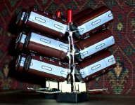
I've been working on the amp a bit every night. The cute but deadly power supply has now had a redo for better power line filtering and mainly for safety reasons. I would like the opportunity to survive while tinkering with the amplifier.
Redo! Sorry, I couldn't imagine up any reliable "Auto Adjust Bleeder" so I ditched modern design entirely. Meanwhile, back at the 1970's. . .
Although visually very similar, the power supply has been rebuilt to a standard Center Tap design with One KBPC2504 rectifier snubbed by 4 of 10nF inexpensive lossy polyester dip caps. As seen previously, there are 6 of decent 2200uF and 1 of 100nF lossy polyester dip cap per each rail.
Close to the rectifier there are two of 2.7k 1/2w resistors hooked to 0v center tap at the input side of the power supply. Both of the 2.7k resistors has its own 30ma rated Bright Amber LED from resistor to rail. Of course there is an LED attached to both rails. That is 290mw per each rail (counting LEDs and resistors). With amplifier (and its speaker load) attached, the power supply drains instantly, as conveniently verified by the amber LED's for safety. If speaker load is omitted, the LED's stay on so that fingers stay away.
Benefit:
This is less hazardous than the previous attempt. After this redo, the output voltage holds steady and same for both rails. The new EI Core transformer and the redone power supply both stay cool and silent while running.
New question:
Should I add an additional "tank section" close to the amplifier, perhaps 35v 10,000uF caps on both rails?
the very simplest I can imagine is a low voltage light bulb. Cold filament resistance is ~ 1/3rd of hot filament resistance. Just match the bulb/s voltage to the full PSU output voltage.I couldn't imagine up any reliable "Auto Adjust Bleeder"
When the PSU is running at full voltage the bulb filament is hot and bleed current is set by the hot bulb parameters.
after shutdown the voltage falls and the bulb cools and the resistance drops and the bleeder tries to pull a more constant current rather than an exponentially reducing current. When down to just a volt or two the bulb will be drawing ~3times the current that a fixed resistor bleeder would be able to.
More complicated methods, adjusting the bleed current to flow only after loss of mains power. This could use FET switches to bring in stepped resistances controlled by window comparators.
A simple mechanical relay could just return to normally closed on loss of power and the bleeders drain the caps.
Last edited:
- Status
- This old topic is closed. If you want to reopen this topic, contact a moderator using the "Report Post" button.
- Home
- Amplifiers
- Chip Amps
- Need help with Triple Parallel LM1875 dynamics amplifier.