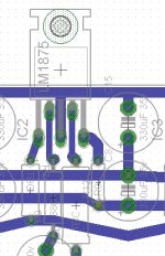
Section of Quad board
I wanted to show a layout section that would fit 8 or 12 of LM1875 amplifier into 100x100mm. I was new to using Eagle (#&%@!!), and while experiencing the torture of the slowest way to promote bad layout ever invented, I am also quitting smoking and was going postal. Eagle? No. Snail. Egads! Is there not something a bit quicker and more layout centric?
Shown are normal size components.
35v 330uF for LM1875 fits as does 35v 220uF for alternative chips; and in either case, the 100nF are under board.
The feedback resistor is under board as is typical of chip amplifier applications.
Attachments
I started using Google Sketchup, I never could find a fast easy way to draw electronics until now.
Pro's - fast, you can draw your whole project in 3D.
Cons- I don't know if their is a direct way to print off PCBs, you would have to convert the file somehow to another format, if needed. Example, a sketchup file would have to be converted to run a CNC machine. Not much of a con as is is doable.
Pro's - fast, you can draw your whole project in 3D.
Cons- I don't know if their is a direct way to print off PCBs, you would have to convert the file somehow to another format, if needed. Example, a sketchup file would have to be converted to run a CNC machine. Not much of a con as is is doable.
Feedback values, and current effect
1). Feedback-shunt resistor range: 820R to 3.3k (more commonly 820R to 2.7k)
2). NFB cap range corresponding to functional value: Based on 2.7k feedback-shunt with 220uF NFB cap, if the resistor value goes to half, double the cap value.
Nearby figures work conditionally (trim primarily with input cap, not NFB cap).
3). Possible feedback resistor values range from 7.5k to 115k, (more commonly 7.5k to 68k) depending on other factors, such as. . .
4). gain between 10 and 43 (more commonly 10 to 35).
It would be nice to see designs where the above 4 conditions are all true, unless there's a good reason for an exception.
For example LM675 is inherently an exception due to low gain.
More discussion (effect on current, sound):
The effects on audio from using a voltage divider, L-Pad on a tweeter are exactly the same as or similar to effects on audio possible from the gain setting resistors of the audio amplifier, which is also a voltage divider.
As can happen with a tweeter, some of the possibilities are unfortunately dull with more impact, some are pretty with unfortunately less impact, some have a higher crossover point, and some have an open but low resolution that doesn't promote a sense of space. The voltage divider also adjusts series current--low value resistors for more current, high value resistors for less current. A wide variety of effects are possible, but it seems that the most desired collection of effects isn't simultaneously available all at the same time.
Thanks man!I reckon one could hand draw 10 copies of your PCB and etch all 10 copies quicker than you could use Eagle to create a matching layout for your through hole discrete components.
Economies of scale?
.....until you want to get a couple properly made then you have to do them up anyway ")
have to admit it does take a while to get all the traces correct
maybe have a look at sprint DWB - thats for penning boards minus schematics
horses for courses i guess
got your point DWB - will see what i can brew up
have to admit it does take a while to get all the traces correct
maybe have a look at sprint DWB - thats for penning boards minus schematics
horses for courses i guess
got your point DWB - will see what i can brew up
It is time for me to explore the 1875 chipamp. I will be ordering 10 of them plus a bunch of 0.1% resistors from Mouser. It is my intention to build a parallel 1875 amplifier to take advantage of lower distortion from less loading of the chip and ability to drive "difficult" loads.
The circuit in post number 5 is a starting point. I intend to reduce gain to around 12. I thrashed out compensating them for unity gain in passband but the 1875 just doesn't have enough GBP (area under Bode plot) to make it worthwhile. I couldn't work out a practical, theoretically stable unity gain configuration; everything I tried (starting compensation @ 100 kHz to not interfere with the audio band) intersected the Bode plot at 40 dB/decade slope. But if anybody disagrees with my conclusion, please let me know!
So I have a couple of simple questions.
1) Is there any advantage (or disadvantage) to using an opamp front end and enclosing the circuit in a global feedback loop with a global gain of around 15 while keeping the local nested gain of the outputs at 12?
2) Is there any advantage (or disadvantage) to DC nulling each chip individually?
Any other tips or omissions are much appreciated. Thank you.
Yes Andrew, I considered that. It's no big deal. I have a nice quantity of metallised polyester caps (I bought a NOS assortment of capacitors for $30- great deal and very useful assortment) , but they are physically large and I'm trying to go small and simple.
I don't want to use servos for reasons listed above.
I would like your opinion on using the circuit basically "as-is" vs employing an op amp front end and global feedback. Is there any benefit? Thank you.
I don't want to use servos for reasons listed above.
I would like your opinion on using the circuit basically "as-is" vs employing an op amp front end and global feedback. Is there any benefit? Thank you.
AndrewT's information is correct in theory and in practice.
Forcing a matchup is especially needed for building the Triple and Quad parallel versions. . . Otherwise, the ballast resistors are excessive, which makes a guitar amp, not a home hi-fi.
Here's two other bits of information.
Nesting (composite):
http://www.diyaudio.com/forums/chip-amps/138762-lm1875-nested-gainclone.html <--link
Supply:
For durability, current limited supply is advisable (required), such as with transformer sized at 1a per chip if monoblock/dualmono or 0.5a per chip if stereo. The LM1875 does not have the noisy Spike system protection scheme, so the current limit protection must be installed by external means for the chip to survive long term use. Reference point, 36va 18+18vac 1a with solo LM1875 monoblock, dualmono, or stereo. Dualmono preferred.
Last edited:
It is time for me to explore the 1875 chipamp. I will be ordering 10 of them plus a bunch of 0.1% resistors from Mouser. It is my intention to build a parallel 1875 amplifier to take advantage of lower distortion from less loading of the chip and ability to drive "difficult" loads.
The circuit in post number 5 is a starting point. I intend to reduce gain to around 12. I thrashed out compensating them for unity gain in passband but the 1875 just doesn't have enough GBP (area under Bode plot) to make it worthwhile. I couldn't work out a practical, theoretically stable unity gain configuration; everything I tried (starting compensation @ 100 kHz to not interfere with the audio band) intersected the Bode plot at 40 dB/decade slope. But if anybody disagrees with my conclusion, please let me know!
So I have a couple of simple questions.
1) Is there any advantage (or disadvantage) to using an opamp front end and enclosing the circuit in a global feedback loop with a global gain of around 15 while keeping the local nested gain of the outputs at 12?
2) Is there any advantage (or disadvantage) to DC nulling each chip individually?
Any other tips or omissions are much appreciated. Thank you.
The only way I can think of, offhand, would be to simply attenuate the input signal with a resistive divider, so you could use higher closed-loop gain and still end up with unity gain, overall. Not sure how well or badly that would work.
Here's two other bits of information.
Nesting (composite):
http://www.diyaudio.com/forums/chip-amps/138762-lm1875-nested-gainclone.html <--link
That is something I can work into a parallel nested feedback amplifier. 0.5a per chip if stereo
I'm right on the money
The LM1875 does not have the noisy Spike system protection scheme, so the current limit protection must be installed by external means for the chip to survive long term use.
I have the perfect salvage transformer already mounted in the case
with the iterative capacitor power supply .I understand how you have to limit the current with these things by "right-sizing' the transformer. I like no SPIKE too.
So thanks, Daniel and everybody else. i have some homework to do to bring this thing together.
Fascinating.
For example, most computer sound cards perform poorly when straining at full blast. And here's my radio with the rather lengthy job of turning down the AF Section gain so it won't clip itself. So, are you quoting the maximum advertised output figures without respect to quality; or, do your modern sources simply cost a lot more than mine?
I've actually tried buying more expensive sources, but have received units that had extraneous parts inserted to make the audio signal both louder and worse, quite like that radio. This spendy source ordeal is a prospect that I haven't gotten to work yet--the advertisements, promises and price have not yet been an indicator of quality. So some guidance on that would be much appreciated.
Last edited:
Global gain of 15x? Wow. Did you intend to require an additional preamp? I just mentioned it because with a modern source (digital volume controls clip themselves if turned to max), I'd sure like an amp with a gain of 33x, at least.
Lower gain = higer loop gain = lower distortion. That is why I explored my initial scheme of compensating the 1875 for unity gain in passband (f0 to 100 kHz) and 12 from 100 kHz up- but it did not look practical; there isn't enough area under the Bode plot for me to have the lines intersect @ 20 dB/ decade.
There will be a small board by the volume control with a buffer that can be internally set with an on board switch for either 1 or 2x. Included on this board will be a variable "loudness" circuit, an RFI filter, and DC blocking/ dominant low frequency pole filter.
Figure 2.2 in the PDF explains my compensation scheme (it's really Walt Jung's scheme and it was a useful trick back in the day when fast op amps were cranky). http://www.google.com/url?sa=t&rct=j&q=walter%20jung%20ic%20op%20amp%20cookbook%20frequency%2Fphase%20compensation&source=web&cd=3&ved=0CDgQFjAC&url=http%3A%2F%2Fwww.analog.com%2Fstatic%2Fimported-files%2Fseminars_webcasts%2F36888492358237Section2.pdf&ei=zVptUf6mFaS1ygHTp4CACw&usg=AFQjCNFgkujI8Y_rQR0o1-HIp5ztmlG97w
Later on a preamp with tone controls and input switch (and a video source switch too) will be added.
Last edited:
Really great writing. Readable engineering! Wowza!
Ah, but try a 1k pot AS the feedback-shunt resistor, and then connect a 10k variable resistor (pot with wiper shorted to one of the outside pins) from the wiper of the 1k to amplifier +input. Why? That might be more fun. Miller design based on all voltage concerns, but ironic that current rules the input and will affect your resistor values.
At this point, any explanation from me will get progressively worse, so Ima gonna go find that article from Mooly, with the scope shots and stuff. . . Yep. Found it.
http://www.diyaudio.com/forums/analog-line-level/196461-different-opamp-compensation-technique.html
These plans will do one other thing. The amplifier will be more forwards sounding. Fortunately, the Parallel build also has a somewhat dark voice, which you could choose to "perk up" with your compensation. The amount of compensation to change dark voice to neutral would be very small. I suggest to try it anyway.
I think that your idea might do "money shot" but I also think that you're going to want a "trimmer party" to find it.
Really great writing. Readable engineering! Wowza!
Me or Walt Jung?
I learned most of my chops from Jung. If you can do it with an op amp, he has a tutorial.
Ah, but try a 1k pot AS the feedback-shunt resistor, and then connect a 10k variable resistor (pot with wiper shorted to one of the outside pins) from the wiper of the 1k to amplifier +input. Why? That might be more fun. Miller design based on all voltage concerns, but ironic that current rules the input and will affect your resistor values.
Forget it. I have simpler tricks that will achieve my objectives.
At this point, any explanation from me will get progressively worse, so Ima gonna go find that article from Mooly, with the scope shots and stuff. . . Yep. Found it.
http://www.diyaudio.com/forums/analo...technique.html
Of course. But my trick is shelving the beta up a decade above 100 kHz, which is kind of exactly the opposite of what you cited. There is not enough gain to acomplish this without instability issues and also looking at the Bode plot on the datasheet there are nasty spikes at the phase transition areas that are probably best left alone.
These plans will do one other thing. The amplifier will be more forwards sounding. Fortunately, the Parallel build also has a somewhat dark voice, which you could choose to "perk up" with your compensation. The amount of compensation to change dark voice to neutral would be very small. I suggest to try it anyway.
I have other plans for voicing the amplifier. I already explored playing with compensation and there just isn't enough loop gain. The Bode plot is screwy and I want to stay in as safe a stability area as possible. The 1875 is not an ideal op amp; not even close. However it is very well suited for its intended applications, and designing with its limitations in mind can hopefully provide some worthwhile results.
I think that your idea might do "money shot" but I also think that you're going to want a "trimmer party" to find it.
You mean tweaking? While I have a comprehensive design in mind and am working on committing it to paper, I will definately tweak it.
I was looking at some of these "audio grade" capacitors. I wonder if there's anything to them. I'm using surplus Nichicon caps right now and they're pretty good. Anyway, those caps are cheap enough so I might pop for some for this project.
Last edited:
- Status
- This old topic is closed. If you want to reopen this topic, contact a moderator using the "Report Post" button.
- Home
- Amplifiers
- Chip Amps
- Need help with Triple Parallel LM1875 dynamics amplifier.