I finally found time to make an LM1875 amplifier which I continued into a composite amplifier.
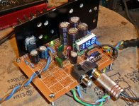
It is made on vero-board. I first placed all the decoupling capacitors and feed-back circuits for the LM1875 ICs as close to the LM1875 pins as possible. Just as Nigel teaches. Then, the remaining components were arranged as close as possible to the other components.
The LM1875 amplifier worked in first attempt. Actually, such a LM1875 amplifier is really well sounding in itself. Good bass-handling and a flawless mid-range is my impression. And, very simple to put together with few peripheral components. I am not the first person to draw this conclusion.
OK, on to convert it into a composite amplifier.
The components for the controlling (double) OP-AMP could not be arranged ideally close to the LM1875 amplifiers. Can't win them all. I did my best and initial outer-loop feed-back components were inserted purely on a feeling. Actually, I again had sound in first go, but not for long. The LM1875s got very hot – obviously self-oscillation above the audible range. The over-heat protection circuit was tested. A perfect functioning for a start was too much to hope for. Playing around with the outer feed-back loop and the speed of the OP-AMP, I came to the conclusion of letting the outer loop feed-back be purely resistive. The capacitive shunt I had put in for a start only made the circuit oscillate. Then, the OP-AMP was slowed down with a capacitive feed-back (only). This time, the finest music and only moderate temperature increase of the heatsink was the result. The sound, that was already very good, seems to be even more transparent and the bass really powerful (within the LM1875 capabilities). The DC-offset at the outputs is a couple of millivolts.
I tried NE5532, LM4562 and OP2134 as controlling OP-AMP. I settled with OPA2134 as the LM4562 is simply too analytic for this use.
A composite amplifier based on LM1875 is possible (as already discussed) and the moderate cost and effort is absolutely worth it. The result has its power limits, that can be overcome with BTL coupling, but the sound can stand up to expensive amplifiers. The LM1875 in standard use is ideal as a first DIY project because it de facto is a 5 pin power OP-AMP and very simple to use. No other control pins to worry about.
Last edited:
I'm going to be a pain but without scope shots of the output into difficult loads or at clipping, it's hard to know if you're really there yet.
Afaik, we only have two published designs for composite amps (the myref and the zd50). And while they're great, they're not without worries wrt clipping and stability.
Afaik, we only have two published designs for composite amps (the myref and the zd50). And while they're great, they're not without worries wrt clipping and stability.
You are fully right. My composite LM1875/OPA2134 amplifier has been constructed on a whim and only tested with two different loudspeaker sets. At good, but not heavy sound levels. The loops have been empirically trimmed and not analyzed in details.
My first aim was to see if I could close an outer control loop and maintain the loop stable with a flat audio band. It seems I have managed that. My construction has not been tested near any corners of operation, yet.
The construction is based on a fully conventional setup so it would be a miracle if my construction would behave much better than, or even as good as, the two designs you refer to. These two designs have probably been subject to thorough scrutiny. Right away, I haven't got time for analysis or thorough test. I use both Zobel and Thiele elements on the LM1875 outputs to leave better conditions for stability.
I describe and suggest my experiment to others such that they know that a control loop can (in practice) be closed and remain stable within moderate operation. I describe how I managed to stop self-oscillation. From there, other may take the experiment further. At least I have an amplifier that sounds good in moderate use. It will serve as basis for further experiments when I find time.
You hint two typical problems for such composite amplifiers: clipping and “difficult loads”. For clipping, is the problem that ringing is generated near the clipping level due to moderate loop stability? For “difficult loads”, do you know what type of loads are typically used as test-loads for testing (moderately) “difficult loads”?
There's probably a lot of people with LM1875 & OPA2134 available.I finally found time to make an LM1875 amplifier which I continued into a composite amplifier.. . . This time, the finest music and only moderate temperature increase of the heatsink was the result. The sound, that was already very good, seems to be even more transparent and the bass really powerful (within the LM1875 capabilities).. . .
Do you have a schematic to share?
A sketch/drawing is fine.
Also, what power voltage did you use?
Thanks!
Sorry, right now I haven't time to draw up a schematics.
I can inform you about the non-trivial characteristics that should make it possible for you to repeat the experiment.
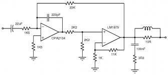
LM1875 amplifiers set to 12 times gain in a non-inverting DC-coupling. Nothing but purely resistive feedback. Zobel and Thiele elements at the output according to the datasheet.
A 6db resistive reduction at the input of the LM1875 part.
OPA2134 in inverting coupling. Feedback from the output of the LM1875 (before the Thiele elements). Purely resistive feedback set to around 18 times overall gain (input of OPA2134 to output of LM1875).
220pF from the OPA2134 outputs back to the inverting OPA2134 inputs.
Elna audio-grade capacitors at the very input set for a high-pass frequency of some 5Hz.
Tested with my variable, linear, symmetrical power supply (high capacity) between 16V and 28V (+/-). Volume levels on my Jamo 707's (8 Ohm) until my wife asked what the h... was going on? No signs of instability. In my subjective perception, very clean sound and a bass that can handle even the lowest frequencies of a church organ (pipe organ).
Among other personal draw-backs, I tend to design circuits with the soldering-iron in my hand. I decide for the detailed circuit as I go along. This is why I do not have a schematics to show you. My initial skills date back from before personal computers would calculate the loop stability. So, the loop stability was decided by empiric means. Even the best planning cannot replace plain luck!
I can inform you about the non-trivial characteristics that should make it possible for you to repeat the experiment.
LM1875 amplifiers set to 12 times gain in a non-inverting DC-coupling. Nothing but purely resistive feedback. Zobel and Thiele elements at the output according to the datasheet.
A 6db resistive reduction at the input of the LM1875 part.
OPA2134 in inverting coupling. Feedback from the output of the LM1875 (before the Thiele elements). Purely resistive feedback set to around 18 times overall gain (input of OPA2134 to output of LM1875).
220pF from the OPA2134 outputs back to the inverting OPA2134 inputs.
Elna audio-grade capacitors at the very input set for a high-pass frequency of some 5Hz.
Tested with my variable, linear, symmetrical power supply (high capacity) between 16V and 28V (+/-). Volume levels on my Jamo 707's (8 Ohm) until my wife asked what the h... was going on? No signs of instability. In my subjective perception, very clean sound and a bass that can handle even the lowest frequencies of a church organ (pipe organ).
Among other personal draw-backs, I tend to design circuits with the soldering-iron in my hand. I decide for the detailed circuit as I go along. This is why I do not have a schematics to show you. My initial skills date back from before personal computers would calculate the loop stability. So, the loop stability was decided by empiric means. Even the best planning cannot replace plain luck!
Last edited:
I've long been planning to try a composite amplifier using LM675, which I believe is close to LM1875 but stable at low gains.
DS quotes a minimum gain of +10, so it's the same as the 1875. Frankly, looking at the respective datasheets, are they exactly the same part?
Edit: [Resolved] LM675: vs LM1875; what's the difference? - Audio Amplifiers Forum - Audio Amplifiers - TI E2E Community (yup!)
Edit edit: IIRC, the 3886 is a faster part, similarly compensated into a G=10, and should be okay with the lower voltages the same as the 1875/675. Speed on the output opamp of a composite is a big_deal.
Last edited:
The LM675 is lower bias. So, I'm wondering if a composite build can redact the higher crossover distortion? Or, if running slightly cooler isn't worth decreased audio quality? You'll get one case or the other.
Good questions....
The only composite amp I have built so far is a current boosted op amp using a push pull follower BJT stage, diode biased, with tip41/42.
I could never bias it heavily enough into AB with the limited current available from the bench supply so settled with the best result I could obtain empirically (low bias, low beta OP, limited base current from op amp).
That meant low watts, but at least on a scope the output looks clean until 4 or 5 watts.
That's my head amp lol
There's probably a lot of people with LM1875 & OPA2134 available.
Do you have a schematic to share?
A sketch/drawing is fine.
Also, what power voltage did you use?
Thanks!
Finally managed to make a schematics. 98% certain on the component values. Not in my labs.
Attachments
The original article is from the November 1992 issue of Radio Electronics/Electronics Now. Pages 38-44. Along with a few textbooks and app notes, that article was a source of inspiration in my development of the Modulus-86. You can find the full issue of RE/EN here: https://ia601701.us.archive.org/15/...s_1992-11/Radio_Electronics_November_1992.pdf
Tom
Tom
Last edited:
I didn't believe I could make it work, but it does ") . Many thanks @ FauxFrench!
. Many thanks @ FauxFrench!
But, beneath all the light, there is some shadow, too. I ordered four OPA2134, but it seems these are not working, or maybe they're fake. With the OPA2134 I get immediately DC (I think its DC, when the speaker cone jumps outward, or what is it? I've got not so much experience yet, so maybe I'm wrong?) on the output when I switch it on.
When I replace the OPA2134 with a NE5532 it seems to work really fine.
Or, maybe my voltage regulator is to "weak" as it can only deliver 100mAh. I don't know what the power consumption of a 2134 is. Could it be more than 100mAh?
. Many thanks @ FauxFrench!But, beneath all the light, there is some shadow, too. I ordered four OPA2134, but it seems these are not working, or maybe they're fake. With the OPA2134 I get immediately DC (I think its DC, when the speaker cone jumps outward, or what is it? I've got not so much experience yet, so maybe I'm wrong?) on the output when I switch it on.
When I replace the OPA2134 with a NE5532 it seems to work really fine.
Or, maybe my voltage regulator is to "weak" as it can only deliver 100mAh. I don't know what the power consumption of a 2134 is. Could it be more than 100mAh?
Attachments
- Home
- Amplifiers
- Chip Amps
- composite amplifiers