David,
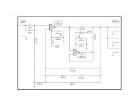
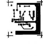
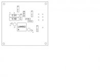
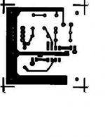
Sorry to take so long but I couldn't find the original files from several years ago, so I had to re-create them. No gerbers, just JPGs of the foil pattern, an X-ray view of the foil pattern, and a parts placement diagram. I used the "toner transfer method" to make my board. I also included a bill of materials for clarity. The single sided board measures 2 1/8" X 2 1/8". On the parts placement diagram which is not perfectly to scale, the decoupling electolytics are the small circles next to the LM4562, and are unlabeled. The decoupling NPO disc caps and the NPO feedback disc cap are all mounted on the bottom of the board right on the opamp pins. There's also a jumper on the bottom side of the board from pin 1 (output of opamp "a") to pin 5 (non-inverting input of opamp "b"). The circuit has a frequency resonse that is ruler-flat from less than 1Hz to in excess of 250kHz. It has extremely low THD, and noise is almost non-existent, and it sounds pretty good too.


View attachment Basic Pre-Amp BOM.txt
Mike
Sorry to take so long but I couldn't find the original files from several years ago, so I had to re-create them. No gerbers, just JPGs of the foil pattern, an X-ray view of the foil pattern, and a parts placement diagram. I used the "toner transfer method" to make my board. I also included a bill of materials for clarity. The single sided board measures 2 1/8" X 2 1/8". On the parts placement diagram which is not perfectly to scale, the decoupling electolytics are the small circles next to the LM4562, and are unlabeled. The decoupling NPO disc caps and the NPO feedback disc cap are all mounted on the bottom of the board right on the opamp pins. There's also a jumper on the bottom side of the board from pin 1 (output of opamp "a") to pin 5 (non-inverting input of opamp "b"). The circuit has a frequency resonse that is ruler-flat from less than 1Hz to in excess of 250kHz. It has extremely low THD, and noise is almost non-existent, and it sounds pretty good too.


View attachment Basic Pre-Amp BOM.txt
Mike
Whoops, so much for clarity! Thanks for catching that, it was a mix-up from alternate versions, correct one below. I also forgot to add that C04 and R05 are baffle step correction of 3dB@480Hz (IIRC) for my particular speakers, so anyone wanting build this will probably need to eliminate them or modify the values to suit thier own system.
View attachment Basic Pre-Amp BOM.txt
Mike
View attachment Basic Pre-Amp BOM.txt
Mike
- Status
- This old topic is closed. If you want to reopen this topic, contact a moderator using the "Report Post" button.