Since these are going to be DIY amplifiers and DIY speakers, I am planning to integrate the amplifiers into the speaker cabinate itself for increased WAF i.e. to reduce the space the whole thing will take, + reduction in number of cables for power and interconnection (Only two wires will go into a speaker (+amp) cabinate – one mains power and one source signal wire (RCA)).
Having some experience of design of such active systems, I'd say that distributing the electronics around is a bad idea from more than one perspective. Does your WAF include sound quality? I mean does your wife care about the sound or only the physical appearance? Having two wires going to each speaker surely will be less acceptable to her than one wire? Admittedly the alternative single wire in this case will be more of a snake
") The main detractor from audiophile sound is noise, and noise is much more of a problem when there are loops, as there will be with two cables to each speaker rather than one. The loops are going to be large in area too, that's not a good sign for great sound as large area loops attract more noise over a wider bandwidth.
The main detractor from audiophile sound is noise, and noise is much more of a problem when there are loops, as there will be with two cables to each speaker rather than one. The loops are going to be large in area too, that's not a good sign for great sound as large area loops attract more noise over a wider bandwidth.Another issue is power supply switching - will you have separate power switches for your 500VA toroids or will you leave them always on? Surely that's a WAF issue too - if she wants to listen when you're not around, how many power switches does she have to throw before she hears something? Does she worry that if she forgets to throw them in the correct sequence she might damage something or get a loud hum or clunk?
abraxalito said:Having some experience of design of such active systems, I'd say that distributing the electronics around is a bad idea from more than one perspective. Does your WAF include sound quality? I mean does your wife care about the sound or only the physical appearance? Having two wires going to each speaker surely will be less acceptable to her than one wire? Admittedly the alternative single wire in this case will be more of a snake The main detractor from audiophile sound is noise, and noise is much more of a problem when there are loops, as there will be with two cables to each speaker rather than one. The loops are going to be large in area too, that's not a good sign for great sound as large area loops attract more noise over a wider bandwidth.
Another issue is power supply switching - will you have separate power switches for your 500VA toroids or will you leave them always on? Surely that's a WAF issue too - if she wants to listen when you're not around, how many power switches does she have to throw before she hears something? Does she worry that if she forgets to throw them in the correct sequence she might damage something or get a loud hum or clunk?
Hi abraxalito, thanks for your reply.
The primary objective is to get better SQ, WAF is important too but SQ takes precedence.
The design is evolving from what I have been reading on this forum and some general thumbrules like
1. Dedicated transformers are better than shared one - here I am not having dedicated ones but there is an intermetiate route of 4 transformers based on current requriements.
2. Building power supply on separate chassis and amplifiers on separate chasis is advisable to minimize the interference.
3. Keeping amplifiers closer to speaker is prefered (with shorter speaker wires)
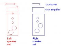
The general overall wiring scheme is as below:
Blue lines are signal and red lines are power

A typical standard Orion installation goes like this (there is only one PSU for both sides of ASP)

What I am thinking is to redraw physical boundry of cases like below

Now few issues you have raised like
1. Start on thump issues (I won't be keeping amps / asp always On)
2. separate power switches and Sequence of ordering - I would prefer to keep it simple (I have small kids who may not follow)
are generic issues of an actively powered setup. I do not have a solution to them yet, but I don't think integrating amps with speakers has got anything to do with it.
I would think that any solution to these issues should work irrespective of whether the amps are separate or integrated physically with the speakers.
You have raised a very valid point about ground loops. So is attaching two 5 channel amplifiers to a single mains an issue, considering that their power supply is separated?
I do not know much about this, but I have seen many setups where multiple amps are connected to same mains supply, how is this different?
Are there any precautions to keep in mind in such installations to avoid ground loops?
The primary objective is to get better SQ, WAF is important too but SQ takes precedence.
OK that's my priority too, so it looks like we've something in common.
1. Dedicated transformers are better than shared one - here I am not having dedicated ones but there is an intermetiate route of 4 transformers based on current requriements.
Where did you learn that a single shared transformer is worse? I can't think why other than it makes grounding more of a challenge. Dual mono is a bit more straightforward but having so many transformers is not the best use of resources. A single larger trafo will always beat multiple smaller ones on price-performance. A large trafo has lower interwinding capacitance than multiple smaller ones, it will also have better regulation, it will be cheaper.
2. Building power supply on separate chassis and amplifiers on separate chasis is advisable to minimize the interference.
What kind of interference? If magnetic then yes, I agree. But the distance needed to reduce magnetic coupling is not so great when toroidals are employed so long as the outlet wires are turned so as to point away from the most sensitive input areas.
3. Keeping amplifiers closer to speaker is prefered (with shorter speaker wires)
I used to think so too. Now I'm not so sure - from the serviceability point of view. Also its best not to subject electronics to more acoustic vibration than is absolutely necessary. With passive XOs, non-bi wired, though this is true.
Now few issues you have raised like
1. Start on thump issues (I won't be keeping amps / asp always On)
2. separate power switches and Sequence of ordering - I would prefer to keep it simple (I have small kids who may not follow)
So its not only WAF, but KAF too
Having amps distant from source components means you're not going to have a common mains switch for everything. So do you implement auto-on (sensing the input signal) ? This adds complexity and you'll always miss the first bar(s) of music that you play. Or do you route the mains supplies from the amps back to the source components? That's lower WAF,KAF having trailing mains across the room. Of course you could go the whole hog and install a dedicated mains spur in the walls...You have raised a very valid point about ground loops. So is attaching two 5 channel amplifiers to a single mains an issue, considering that their power supply is separated?
No, that's not the issue. The issue is the RF loops formed by the long source cables and the mains wiring. You'll definitely need to run balanced interconnect from source to amps to have a hope of reasonable sound, otherwise the loops will be through the 0V pcb tracks of your amps. With balanced the ground can be connected to chassis and thereby to earth. Currents will still flow in those loops but we'd hope that won't infect audio circuitry.
<edit> Had a quck look at your graphics - the weakness of them is that current flows in loops and all your connections are shown as straight lines. Grounding also is an important issue to consider at the design stage if you're aiming for the best sound.
Last edited:
OK that's my priority too, so it looks like we've something in common.
Where did you learn that a single shared transformer is worse? I can't think why other than it makes grounding more of a challenge. Dual mono is a bit more straightforward but having so many transformers is not the best use of resources. A single larger trafo will always beat multiple smaller ones on price-performance. A large trafo has lower interwinding capacitance than multiple smaller ones, it will also have better regulation, it will be cheaper.
Yes, this will be my first and probably last DIY speaker project (for this decade) . And I want the best sound possible as far as practically possible.
AndrewT said:One 5channel amp dedicated to each Orion is far more likely to sound better than 12 or 16chipamps in a common chassis.
Personally I would build stereo amplifiers.
One stereo amp to the tweeter pair. One stereo amp to the woofer pair.
One monoblock to the Mid driver.
Total amp requirement for the 10driver Orions: 4 stereo amps and 2 monoblocks.
I am following Michael's recommendation.Michael Bean said:Andrew recommended building your amps in separate stereo and monoblock boxes which is generally a good idea, it will keep construction complexity down and makes the inevitable troubleshooting much easier. But one way I differ from Andrews' suggestion would be to build a two channel amp for the woofers and a three channel amp for the mid and tweeters for each stereo side, in other words, two amplifier boxes for each channel for a total of four for the whole project instead of the six that four stereo and two monoblcks would require. Here's a block diagram for clarity:
No solution planned yet. Still to think about that.So its not only WAF, but KAF too
All amps are going to be connected from one mains point. In India all mains points are switched, so that switch will be the common switch on.
I would definitely be going with a slow start circuit to control the initial inrush current and also speaker protection circuit on tweeters.
Yes, I understand I may have to run balanced interconnects between the source and the ASP.No, that's not the issue. The issue is the RF loops formed by the long source cables and the mains wiring. You'll definitely need to run balanced interconnect from source to amps to have a hope of reasonable sound, otherwise the loops will be through the 0V pcb tracks of your amps. With balanced the ground can be connected to chassis and thereby to earth. Currents will still flow in those loops but we'd hope that won't infect audio circuitry.
Can you explain please explain "current flows in loops and all your connections are shown as straight lines", obviously each line represents two wires (positive and neutral).<edit> Had a quck look at your graphics - the weakness of them is that current flows in loops and all your connections are shown as straight lines. Grounding also is an important issue to consider at the design stage if you're aiming for the best sound.
This design of integrated speaker and amplifier has been inspired from what Linkwitz has done on Pluto speakers.
ST,
your proposal to integrate the PSU and Crossover and amplifiers into their speaker enclosure sounds well founded.
The two cables to each speaker that you referred to are OK. One is mains cable, the other is signal interconnect.
I do not believe that the signal interconnect needs to be balanced impedance. I would try an unscreened twisted pair (utp), for signal flow and signal return.
Most serious active speakers have separate power supplies per speaker. And there are enough examples of really good sounding models to resolve all doubts about such a configuration.
Mechanical vibrations are actually a killer argument against having electronics in a speaker cabinet. You need stable (thick) PCBs, a good control of the solder quality. You should mount the electronics in a separate compartment to protect them against vibration transmission by air. And if you support the PCBs on some kind of dampers, that should help against mechanical vibration transmission.
Balanced cables are coming more and more into fashion, but there are many active speakers with unbalanced cables around that sound reasonably good. If you don't own devices with balanced interconnects already, it makes sense to try unbalanced cabling first. Refit balanced cables only, if you can confirm that the unbalanced setup causes trouble that a balanced configuration can solve.
I am a bit at a loss about how a mains cable and a signal cable going to an active speaker should create RF loops when a single signal cable should not. But hey, you can always use RF filters at the amps' in- and outputs, just like the pros do, so no need to worry.
Your modifications to the Orion's cabinet need some consideration. The PSU case will influence the rear reflections of the midrange speaker. Lifting the Orion on top of an amp case will have the effect that the tweeters aim above your ears instead of aiming right at them when you sit on a sofa. It would also be better to have the transformers at the bottom, so that the weight stabilises the speaker. On the other hand, the heatsinks for three BTL and two SE channels may add up to some considerable weight also.
Can you explain please explain "current flows in loops and all your connections are shown as straight lines", obviously each line represents two wires (positive and neutral).
No, that's not at all obvious. If so then which of the pairs are the grounds? You need to send bipolar signals to the drivers so need +,- and ground wires (that's three wires) to the amps but you show only one pair (positive and neutral) to each.
Thanks AndrewT, Pacificblue, mymindinside, abraxalito for your inputs!
Yes, vibrations is one thing I did not seriously factor in. While transmission by air will not be much, physical one through structure might be an issue. Are you familiar with any kinds of dampers for this?
Seating height I can manage by altering the furniture but rear reflection still might be an issue. I don't think it should impact much, as there seem to be significant clearance but I know little about these things!
Regarding the weight of heat sinks, each speaker will have at least 6 lbs of heat sink to keep 8 LM3886 cool. I think that along with woofer weight itself should be sufficient to stabilize the speaker.
Mymindinside, I have 2-3 components but most of them I am yet to procure, so your directions will help. I am in Bangalore.
Mechanical vibrations are actually a killer argument against having electronics in a speaker cabinet. You need stable (thick) PCBs, a good control of the solder quality. You should mount the electronics in a separate compartment to protect them against vibration transmission by air. And if you support the PCBs on some kind of dampers, that should help against mechanical vibration transmission.
Your modifications to the Orion's cabinet need some consideration. The PSU case will influence the rear reflections of the midrange speaker. Lifting the Orion on top of an amp case will have the effect that the tweeters aim above your ears instead of aiming right at them when you sit on a sofa. It would also be better to have the transformers at the bottom, so that the weight stabilises the speaker. On the other hand, the heatsinks for three BTL and two SE channels may add up to some considerable weight also.
Yes, vibrations is one thing I did not seriously factor in. While transmission by air will not be much, physical one through structure might be an issue. Are you familiar with any kinds of dampers for this?
Seating height I can manage by altering the furniture but rear reflection still might be an issue. I don't think it should impact much, as there seem to be significant clearance but I know little about these things!
Regarding the weight of heat sinks, each speaker will have at least 6 lbs of heat sink to keep 8 LM3886 cool. I think that along with woofer weight itself should be sufficient to stabilize the speaker.
Mymindinside, I have 2-3 components but most of them I am yet to procure, so your directions will help. I am in Bangalore.
Something like this should be available where you live. It takes some trial-&-error to find the right size and rubber for the weight of your electronics and the vibration frequency range. You also find them for audio devices with more appealing looks and accordingly higher prices.Are you familiar with any kinds of dampers for this?
Well, if you still sit comfortably afterwards that is a possible solution.Seating height I can manage by altering the furniture but rear reflection still might be an issue.
About the rear reflection, if you want to avoid building both versions and comparing them, you might ask Dr. Linkwitz himself or put the question in the Orion Forum.
Thanks Pacificblue!
I got the idea about the fastners.
Already posted this on the Orion Forum, here.
Mr. Linkwitz usually does not answer questions related to altering his designs. I can understand that, with so many people getting so many ideas, it would be difficult for him to do so... But other Orion owners are very helpful and share from their experiences.
Kevin has offered to try out blocking the rear reflection partially by keeping a 4" obstruction and share his observation, if there is a perceptible difference it makes to the sound.
Last edited:
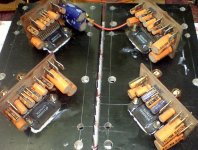
Buddy, making a multi-channel amplifier is not an easy task. On paper you can plan so easily as i saw the 2 colored block diagrams. But as you try to arrange the actual things like power supply rectifier , caps, amplifier PCBs, inlet and outlet cables, it become a difficult thing to manage.
Check out my 5.1 system based on LM4780 and see the complexity, i tried to keep it simpler on paper but as the hardware settled down, it gave me a big headache to complete the system. -
5.1 LM4780 based amplifier.
so in ur case my suggestion will be make individual crossover circuit enclosure separately for each L & R speaker set.
and another enclosure for only power amplifiers, again seperatly for L & R.
it may be a little costly but will give you easy milestones to complete and easy to make.
Check out my 5.1 system based on LM4780 and see the complexity, i tried to keep it simpler on paper but as the hardware settled down, it gave me a big headache to complete the system. -
An externally hosted image should be here but it was not working when we last tested it.
5.1 LM4780 based amplifier.
so in ur case my suggestion will be make individual crossover circuit enclosure separately for each L & R speaker set.
and another enclosure for only power amplifiers, again seperatly for L & R.
it may be a little costly but will give you easy milestones to complete and easy to make.
Attachments
Buddy, making a multi-channel amplifier is not an easy task. On paper you can plan so easily as i saw the 2 colored block diagrams. But as you try to arrange the actual things like power supply rectifier , caps, amplifier PCBs, inlet and outlet cables, it become a difficult thing to manage.
Check out my 5.1 system based on LM4780 and see the complexity, i tried to keep it simpler on paper but as the hardware settled down, it gave me a big headache to complete the system. -An externally hosted image should be here but it was not working when we last tested it.
5.1 LM4780 based amplifier.
so in ur case my suggestion will be make individual crossover circuit enclosure separately for each L & R speaker set.
and another enclosure for only power amplifiers, again seperatly for L & R.
it may be a little costly but will give you easy milestones to complete and easy to make.
Thanks for an upfront caution Kuldeep,
That is one of the reason I am separating the amplifier power supply from the amplifiers in a separate enclosure. (If you take the PSU out of your 5.1 ch than you will see that amplifier section becomes significantly less cluttered).
The ASP also I am splitting left and right and would place them separately on the two sides. Though to keep the wiring short & simple I intend to keep respective ASP in the respective amplifier case itself.
Of course all this is initial planning and many things might change / relocate as the execution challenges start showing up, though I would try to keep them minimal
100 Watt Bridge Amplifier for Woofer with Soft Start Mute circuit
It's been some time now. I have been working on the circuit for the bridge layout. I am planning to use following for each side speaker (Actively power Linkwitz orion speakers, more context in first post)
1. Two single LM3886 amps for two tweeters independently (Seas Millennium Tweeter, 5 ohm, frequency = 1440 hz to 20khz)
2. Two LM3886 in bridge mode for one mid range speaker (Seas W22EX001, 8 ohm, frequency = 92 Hz to 1440 hz)
3. Two LM3886 in bridge mode for each woofer (there are 2 woofers per side, so there will be 2 bridge amps made up of 4 LM3886) - (Peerless 10" XLS Woofer, 8 ohm, frequency = 20hz to 92 hz)
Below is the circuit diagram that I have designed for the Bridge Circuit for the mid range. (for woofer the caps marked in blue will be dropped). Each of these bridge amps should be capable of giving 130W clean output at 28V Rail. The total gain of bridge amp is designed to be 26.
Please review this circuit layout and share your views on this...

Following are the notes around this design
1) Cinp, Ci1p & Ci2p are premium Polypropylene Capacitors for reducing distortion at high freq.
2) Lower -3dB roll off with CinRin (Being HPF)=0.482Hz
3) Lower -3dB Roll off at input of Non Inv Amp with Ci1&Ri1=1.59Hz
4) Lower -3dB Roll off at input of Inv Amp with Ci2&Ri2=1.59Hz
5) Cf1 & Cf2 are for preventing high frequency instability at low gain, giving high frequency -3dB gain roll off at 991Khz. (Beyond 991 Khz gain reduces @ 12dB/Octave).
6) L1//R1 and L2//R2 provide high impedance to high freq, so isolates Amplifier at high freq from Capacitive Load due to speaker & connecting cable so prevent oscillation due to the capacitive load. 3dB pt is at 2.27Mhz beyond which impedance of L1 & L2 become high.
7) Rsn1&Csn1, and Rsn2&Csn2 Filter High Freq Noise with -3dB roll off at 589 Khz.
8) R9&C3 is LPF with -3dB cut off at 498 Khz. It filters High Freq Noise at Input
9) Since Rf1=Rb1 for Non Inv Amp, DC Offset Voltage is under control.
10) LF411ACN forms Buffer (Voltage Follower) isolates low input impedance of Bridge Amp from loading the low source impedance
11) C1 and C2 filters high frequency noise at Inputs of each power IC
Note: Value of Cin, Ci1 & Ci2 given is for woofer bridge amp and for midrange amp it would be one tenth of the value
It's been some time now. I have been working on the circuit for the bridge layout. I am planning to use following for each side speaker (Actively power Linkwitz orion speakers, more context in first post)
1. Two single LM3886 amps for two tweeters independently (Seas Millennium Tweeter, 5 ohm, frequency = 1440 hz to 20khz)
2. Two LM3886 in bridge mode for one mid range speaker (Seas W22EX001, 8 ohm, frequency = 92 Hz to 1440 hz)
3. Two LM3886 in bridge mode for each woofer (there are 2 woofers per side, so there will be 2 bridge amps made up of 4 LM3886) - (Peerless 10" XLS Woofer, 8 ohm, frequency = 20hz to 92 hz)
Below is the circuit diagram that I have designed for the Bridge Circuit for the mid range. (for woofer the caps marked in blue will be dropped). Each of these bridge amps should be capable of giving 130W clean output at 28V Rail. The total gain of bridge amp is designed to be 26.
Please review this circuit layout and share your views on this...
Following are the notes around this design
1) Cinp, Ci1p & Ci2p are premium Polypropylene Capacitors for reducing distortion at high freq.
2) Lower -3dB roll off with CinRin (Being HPF)=0.482Hz
3) Lower -3dB Roll off at input of Non Inv Amp with Ci1&Ri1=1.59Hz
4) Lower -3dB Roll off at input of Inv Amp with Ci2&Ri2=1.59Hz
5) Cf1 & Cf2 are for preventing high frequency instability at low gain, giving high frequency -3dB gain roll off at 991Khz. (Beyond 991 Khz gain reduces @ 12dB/Octave).
6) L1//R1 and L2//R2 provide high impedance to high freq, so isolates Amplifier at high freq from Capacitive Load due to speaker & connecting cable so prevent oscillation due to the capacitive load. 3dB pt is at 2.27Mhz beyond which impedance of L1 & L2 become high.
7) Rsn1&Csn1, and Rsn2&Csn2 Filter High Freq Noise with -3dB roll off at 589 Khz.
8) R9&C3 is LPF with -3dB cut off at 498 Khz. It filters High Freq Noise at Input
9) Since Rf1=Rb1 for Non Inv Amp, DC Offset Voltage is under control.
10) LF411ACN forms Buffer (Voltage Follower) isolates low input impedance of Bridge Amp from loading the low source impedance
11) C1 and C2 filters high frequency noise at Inputs of each power IC
Note: Value of Cin, Ci1 & Ci2 given is for woofer bridge amp and for midrange amp it would be one tenth of the value
Last edited:
Hi,
again an upfront warning, be very careful when placing resistors on the PCB. One IC is in non-inv config, other is in inverting config, so the resistor set have different values for inv & non-inv.
What I'll suggest you is to make both the ICs in same configurations and add a unit gain phase changer ic just after the buffer. This will help in easy up your bill of material and independently check both the power ICs for sound.
What I'll suggest you is to make both the ICs in same configurations and add a unit gain phase changer ic just after the buffer. This will help in easy up your bill of material and independently check both the power ICs for sound.
Hi Kuldeep,
I considered that idea, however as per National Note - Overture Series High Power Solutions, using output of one amp as the input to second inverting amplifier inherently possess higher TD and noise that will degrade the sound quality. Therefore I did not pursue that path.
Cf1 and Cf2 should be bigger to fit to C1 and C2. The LM3886 has a typical GBWP of 8 MHz, which leads to a GBW of ~563 kHz for your gain of 14,2 times. A roll-off at 991 kHz has no effect. Try 47 pF and provide space for a series resistor for that cap.
2 x power = 3 dB, 2 x voltage = 6 dB, because double the voltage will lead to double the current for a given impedance, so the total voltage gain of your bridge will be 29 dB.
Single op amps, like the LF411, usually have compensation pins, which provide an easier and more reliable way to adjust the offset, than your R3/R4 configuration. Check the datasheet for details.
For offset adjusting of the complete bridge amp, skip R6 and R8 and replace R7 with a 20k trimmer. Adjust the offset, then replace the trimmer with a fixed resistor of the corresponding value.
You could also try the Simplest Ever Bridging Adapter for Amplifiers to use two non-inverting chip amps without inverter and/or buffer op amps to make your life easier.
Cf1 and Cf2 should be bigger to fit to C1 and C2. The LM3886 has a typical GBWP of 8 MHz, which leads to a GBW of ~563 kHz for your gain of 14,2 times. A roll-off at 991 kHz has no effect. Try 47 pF and provide space for a series resistor for that cap.
Cf1 and Cf2 (are in feedback path and affect gain characteristic) they have no correlation with C1 and C2 (for suppression of high frequency noise at input). If we provide a resistance in series with Cf1 & Cf2 capacitors the overall gain gets reduced further at higher frequency, and gain response is also not flat, which is not desirable. I will consider increasing Cf1 and Cf2 to around 12 to 15 pF keeping in mind that it does not short the input terminals to output terminals through C1 and C2.
2 x power = 3 dB, 2 x voltage = 6 dB, because double the voltage will lead to double the current for a given impedance, so the total voltage gain of your bridge will be 29 dB.
What you are saying about power is in single mode not in bridge mode. In bridge mode the virtual load which one IC will see is half the value of load resistance. Hence each IC will give 23db power (14 gain), therefore 2 ICs will give 26 db gain (total gain of 28).
Thanks, checked the data sheet, pin 1 and 5 can be used for offset balance, which I will use. However the maximum supply that chip can take is only +/-22V whereas my voltage rail is +/-28V.Single op amps, like the LF411, usually have compensation pins, which provide an easier and more reliable way to adjust the offset, than your R3/R4 configuration. Check the datasheet for details.
Can you explain how to adjust +/- voltage at the input pin of OP Amp for offset management?For offset adjusting of the complete bridge amp, skip R6 and R8 and replace R7 with a 20k trimmer. Adjust the offset, then replace the trimmer with a fixed resistor of the corresponding value.
Also high resistance (20k) will increase the input noise, which at present is not there, as only 100ohm resistance is being used. I have taken this circuit from National AN31
You could also try the Simplest Ever Bridging Adapter for Amplifiers to use two non-inverting chip amps without inverter and/or buffer op amps to make your life easier.
I considered that idea, however as per National Note - Overture Series High Power Solutions, using output of one amp as the input to second inverting amplifier inherently possess higher THD and noise that will degrade the sound quality. Therefore I did not pursue that path.
I propose that you check the circuit in Spice to see the effect. C1 and Cf1 form a frequency-dependent voltage divider and changing either will affect the entire response. Their values need to fit to each other.Cf1 and Cf2 (are in feedback path and affect gain characteristic) they have no correlation with C1 and C2 (for suppression of high frequency noise at input).
That’s the idea of op amp compensation, to shape the gain in a way to avoid oscillation. If you don’t need the resistor, don’t put it in, but you should at least provide the space for it, just in case.If we provide a resistance in series with Cf1 & Cf2 capacitors the overall gain gets reduced further at higher frequency, and gain response is also not flat, which is not desirable.
14 x voltage gain is 23 dB, 28 x voltage gain is 29 dB, see dB calculator.What you are saying about power is in single mode not in bridge mode. In bridge mode the virtual load which one IC will see is half the value of load resistance. Hence each IC will give 23db power (14 gain), therefore 2 ICs will give 26 db gain (total gain of 28).
Double the voltage through a given load gives double the current. 2 x U x 2 x I = 4 x P. Four times power is also a difference of 6 dB.
Yes, you will need a separate power supply for the op amp.Thanks, checked the data sheet, pin 1 and 5 can be used for offset balance, which I will use. However the maximum supply that chip can take is only +/-22V whereas my voltage rail is +/-28V.
The op amp’s bias current through the resistor produces a voltage drop across it. The right resistor value will lead to the same offset on both amp inputs, which leads to 0 output offset.Can you explain how to adjust +/- voltage at the input pin of OP Amp for offset management?
Will the increased input noise become audible at all? If not, take advantage of the situation and reduce the offset as far as possible.Also high resistance (20k) will increase the input noise, which at present is not there, as only 100ohm resistance is being used.
There is no inverting amplifier in Elliott’s bridge adapter. There are only two equal non-inverting amps and two additional resistors. With that method you can skip the LF411 input buffer, which should improve THD and sound quality according to National’s theory, and you save the additional power supply for the op amp.I considered that idea, however as per National Note - Overture Series High Power Solutions, using output of one amp as the input to second inverting amplifier inherently possess higher THD and noise that will degrade the sound quality. Therefore I did not pursue that path.
- Status
- This old topic is closed. If you want to reopen this topic, contact a moderator using the "Report Post" button.
- Home
- Amplifiers
- Chip Amps
- LM3886 based 8 Channel amps for linkwitz Orion