Bought this 4x TDA7294 kit from ebay & hooked it up to 2x24 600VA toroidal transformer. When I powered it up, it works, but also produces hummmm sound in speakers with & without anything connected at input. What could be a problem?
Also, how to increase bass response?
Also, how to increase bass response?
Last edited:
Increase the value of Bootstrap Capacitor, It should be 110uf minimum 220 uf better
Bought this 4x TDA7294 kit from ebay & hooked it up to 2x24 600VA toroidal transformer. When I powered it up, it works, but also produces hummmm sound in speakers with & without anything connected at input. What could be a problem?
Also, how to increase bass response?
Bought this 4x TDA7294 kit from ebay & hooked it up to 2x24 600VA toroidal transformer. When I powered it up, it works, but also produces hummmm sound in speakers with & without anything connected at input. What could be a problem?
Also, how to increase bass response?
A picture of your setup would probably help.
increasing the Bass response could make the Hum sound Louder........... it works, but also produces hummmm sound in speakers with & without anything connected at input. ...............how to increase bass response?
You almost certainly have an error in the grounding or in the PSU.
Read
Audio Component Grounding and Interconnection - diyAudio
Bought this 4x TDA7294 kit from ebay & hooked it up to 2x24 600VA toroidal transformer. When I powered it up, it works, but also produces hummmm sound in speakers with & without anything connected at input. What could be a problem?
Also, how to increase bass response?

Make sure that the AC pair is twisted tightly together, right up to the screw terminals. Also twist tightly together your input pairs, right up to the terminal block. And ditto for your output pairs. (Or use shielded twisted pair cable.)
Make sure none of those three pairs get near each other, or any other part of the circuit.
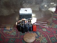
What are the values of the two large-ish red box capacitors, near the input terminal block? And what are the values of the six electrolytic capacitors that are in a line, near the four chipamps?
Last edited:
I've moved on to APEX TDA7294 amp design, works perfectly. But, if it is possible to debug this one, why not.
If memory serves, large-ish red box caps are 2.2uF Small ones are 22uF.
About twisting cables etc - it isn't that kind of hum. It's constant, quite loud and annoying. Maybe theese TDA7294 chips are fake or the PCB design is bad one.
If memory serves, large-ish red box caps are 2.2uF Small ones are 22uF.
About twisting cables etc - it isn't that kind of hum. It's constant, quite loud and annoying. Maybe theese TDA7294 chips are fake or the PCB design is bad one.
Hi there,
I have the same board with exactly same problem as you described. I think the amp is self-oscillating, it is dependent on what is connected to the input and also on type of PSU. To me it is something between the hum and a high freq buzz. The heatsink become quickly hot (in comparison with 3875/3886 gainclones).
On PSU side I've tried different R-Core and toroidal transformers (2x15, 2x18 and 2x24V, 200-500VA) and also replaced the transformer with the 2x24V/6A switching power supply.
The type of transformers has very little influence, but with the SPSU the hum was almost gone, the buzz were still there.
I've tried then to add more smoothing caps (2x20,000uF/40V) but it had again a little or no influence on the humm/buzz.
Maybe a wrong PCB design/wrong parts? - I haven't had a chance to investigate deeper for the moment...
Now we're getting somewhere. We should have asked about the frequency of the "hum", I guess, instead of assuming that the word "hum" meant 50-60 Hz from the AC power, as it typically does.
I would first look at the manufacturer's datasheet and make sure that it was designed within the normal stability regime. Then you could try adding some small pF capacitors in parallel with the feedback resistors, to see if that changes it. And try 220 pF or so across the + and - inputs, to filter any RF that might be causing the problem.
It would REALLY help to see a schematic of one chip's amplifier circuit portion of the board. It might just need higher gain, for example, or a different capacitor value somewhere. You could try holding the leads of another 22 uF capacitor across one of the existing ones, for example, if you're extremely careful (unless they just bypass the power pins; then don't bother). But with a schematic, someone could probably just TELL you what was wrong, if it's just designed with improper component values.
Now that I look at it, there aren't even enough bypass caps for the power pins! That could be the problem, right there! Are they not bipolar chips?
They must(!) have an electrolytic AND a small ceramic (or small film cap), typically something like 100 uF and 0.1 uF in parallel, from EACH power pin to ground, for each and every power pin of each and every chip, connected as close to the power pins as possible, and NOT connecting to the same ground conductor that is used for the input resistor's ground reference point. Is that not what this board has? Or are they underneath, maybe?
Also, what does each chip's negative input pin connect to? If there is any length of PCB trace or wire, there, it might have enough stray capacitance to make the circuit unstable, so it oscillates. For something like that, a small (100 Ohms or less) resistor in series with the pin (right near the pin), to isolate the pin from the stray capacitance of any length of conductor, could fix it.
And still, at least part of the hum could be from wire pairs not being twisted, or worse, from PCB trace pairs that are separated but should not be. Those could be fixed by bypassing them with wires that get glued on or near the other member of the pair, but how much did this thing cost? It might not be worth it, unless it is totally unusable as is and you don't mind experimenting.
Those are all just guesses so I wouldn't spend much time on them before reverse-engineering and posting the schematic for the portion of the circuit that corresponds to the schematic in the manufacturer's datasheet. If i get time, I will try to enlarge the picture and look at the datasheet to try to correlate with the picture and figure out what is connected to what, etc.
Last edited:
If you had the use of an oscilloscope, it would really help. There might be multiple problems, such as needing snubbers in the rectifier section or other places. A scope would make it possible to choose optimal values for snubber components, easily. And a scope would make any oscillation obvious, too. But the high temperature is a pretty good indicator of that, often, or at least sometimes.
. . . The heatsink become quickly hot (in comparison with 3875/3886 gainclones).
Wow!! That's really weird.
TDA7294 should run cool, even on "cost effective" heatsinks.
I don't exactly have anything to contribute other than adding a couple 220uF caps directly at the predrive power pins (7, 8) and then also adding a single 2uF, from pin 7 to pin 8, was required to chill out my own TDA7294.
Since they crammed so much stuff on one board, you might have to "simplify" it quite a bit until the problem is found.
When I Get home from work tonight I will take HiRes pictures of the front and back of my PCB (same as the one in question).
I am starting to get very interested in the outcome now.
I heard the same frequency/type Buzz/Hum from my Audiosector LM4780 kit the FIRST time I turned it on, never since.
This TDA7294 seems to have the same sound just constant.
When I would crank the volume up the hum/buzz was inaudible over the music.
I don't know if that helps or not but in my experience the hum/buzz was input drive independent.
Last edited:
If you had the use of an oscilloscope, it would really help. There might be multiple problems, such as needing snubbers in the rectifier section or other places. A scope would make it possible to choose optimal values for snubber components, easily. And a scope would make any oscillation obvious, too. But the high temperature is a pretty good indicator of that, often, or at least sometimes.
Hi,
I should have an old Russian oscilloscope in a grange (1 channel, up to 2Mhz, screen 3"x2"
") - I will try to have a look and if it is still working I could post some pictures - do you have any suggestions about what I have to measure?
- I will try to have a look and if it is still working I could post some pictures - do you have any suggestions about what I have to measure?Hi there, as my oscilloscope is still alive (using probably the good old russian military grade components I've checked what the huming/buzzing output looks like.
As it is rather a random mode noise, it was not easy to get a clear picture on the oscilloscope. I was able to find the 50Hz (distorted sinus) hum component. There were also the HF component but at the limit of my oscilloscope abilities (looked like the 50MHz+ sinus).
As far as I was able to check the PCB (the top layer is partially hidden by capacitors and relays) it follows the "Figure 25: Bridge Application Circuit" from the TDA7294 datasheet with a few exceptions:
* each of the 4 TDA7294 share the same ST-BY/MUTE (so all four TDAs pins "9" interconnected, the same for pins 10)
* the two PSU smoothing Caps of the 10mF/50V each are shared by all 4 TDAs through one relatively thin and long PCB trace, for the Vs+ and same for the Vs-. There is no other bypass capacitors at the Chip or on at the PSU rails.
* the signal ground is connected to the power ground at the signal input GND connector, but also in the middle of the PCB thru 3 vias (?)
* the input capacitors are of 2u2/250V (datasheet value is "0.56uF"), but there is no equivalent part at the input of the slave TDAs (i mean between pins 1-3: only the 22k resistor is implemented)
* the NFB resistor measures 10k (pins 2-14) but this is maybe because of the BTL (unfortunately I'm not able to read the color codes on a blue color resistors...)
I've not checked the Speaker protection part of the circuit.
http://www.st.com/internet/com/TECHNICAL_RESOURCES/TECHNICAL_LITERATURE/DATASHEET/CD00000017.pdf
I've checked what the huming/buzzing output looks like.As it is rather a random mode noise, it was not easy to get a clear picture on the oscilloscope. I was able to find the 50Hz (distorted sinus) hum component. There were also the HF component but at the limit of my oscilloscope abilities (looked like the 50MHz+ sinus).
As far as I was able to check the PCB (the top layer is partially hidden by capacitors and relays) it follows the "Figure 25: Bridge Application Circuit" from the TDA7294 datasheet with a few exceptions:
* each of the 4 TDA7294 share the same ST-BY/MUTE (so all four TDAs pins "9" interconnected, the same for pins 10)
* the two PSU smoothing Caps of the 10mF/50V each are shared by all 4 TDAs through one relatively thin and long PCB trace, for the Vs+ and same for the Vs-. There is no other bypass capacitors at the Chip or on at the PSU rails.
* the signal ground is connected to the power ground at the signal input GND connector, but also in the middle of the PCB thru 3 vias (?)
* the input capacitors are of 2u2/250V (datasheet value is "0.56uF"), but there is no equivalent part at the input of the slave TDAs (i mean between pins 1-3: only the 22k resistor is implemented)
* the NFB resistor measures 10k (pins 2-14) but this is maybe because of the BTL (unfortunately I'm not able to read the color codes on a blue color resistors...)
I've not checked the Speaker protection part of the circuit.
http://www.st.com/internet/com/TECHNICAL_RESOURCES/TECHNICAL_LITERATURE/DATASHEET/CD00000017.pdf
Last edited:
Hence the oscillation. ;-/ Don't we all love a "quick buck" type PCB design?* the two PSU smoothing Caps of the 10mF/50V each are shared by all 4 TDAs through one relatively thin and long PCB trace, for the Vs+ and same for the Vs-. There is no other bypass capacitors at the Chip or on at the PSU rails.
Yummy, a ground loop. If there still is hum once the oscillation is tamed, we'll know where it comes from...* the signal ground is connected to the power ground at the signal input GND connector, but also in the middle of the PCB thru 3 vias (?)
That should mainly influence noise and distortion levels, not make or break operation. Once the circuit starts working, you may want to add another 2u2 in parallel to the 22k.* the input capacitors are of 2u2/250V (datasheet value is "0.56uF"), but there is no equivalent part at the input of the slave TDAs (i mean between pins 1-3: only the 22k resistor is implemented)
Pictures of the PCB as sold on ebay
Just to add photos of those "state of the art PCBs" made in China And it is already a version 2.0
The PCB mention "TDA7293" but four chips are "TDA7294"
https://picasaweb.google.com/lh/photo/oZMhY7KcRAxWzHEd9GEObA?feat=directlink
https://picasaweb.google.com/lh/photo/hgPlFKJXCQilfcDA7gALJw?feat=directlink
Anyway, it should be not so hard to fix it, or? Any suggestions?
Just to add photos of those "state of the art PCBs" made in China
And it is already a version 2.0 The PCB mention "TDA7293" but four chips are "TDA7294"
https://picasaweb.google.com/lh/photo/oZMhY7KcRAxWzHEd9GEObA?feat=directlink
https://picasaweb.google.com/lh/photo/hgPlFKJXCQilfcDA7gALJw?feat=directlink
Anyway, it should be not so hard to fix it, or? Any suggestions?
I guess the first thing I would try is adding the 0.22 uF bypass caps from pins 15 & 8 to gnd and from pins 13 & 7 to gnd. They really should be connected very close to where the pin leaves the device, if possible. And it would help to either connect their other ends to the large ground plane or (probably better) just run new wire(s) to the ground between the main filter caps' ground connections. So you could either use four of them per device, or try four 0.1 uF instead of 0.22 uF, or just use two 0.22 uF per TDA device and hope for the best.
I would then also try adding some large electrolytics connecting to the same places. The datasheet says two 2200 uF per device but you could try whatever is on hand, temporarily, if need be, just to see if it makes a significant difference. You might have to get creative about how to mount and connect them.
If I had to do it, I might be tempted to un-daisychain the power rails and the power ground by running three new wires to each chip (and grinding away the pcb traces for the power supply voltages, near each of the pins). At the least, I would run a new wire or something, or four separate ones, for the decoupling/bypass ground returns (and for any other dirty grounds), or, alternatively maybe, run separate new grounds for the input resistors' ground references. Maybe you could add a bolt somewhere near the filter caps (or wherever worked best), connected to the ground plane only, and use ring terminals to connect the new separate "star" ground returns.
I might also want to wire the output grounds separately, back to the main filter caps' ground area.
On the other hand, starting simple, with the layout as it is now, I'd probably first at least try just temporarily connecting one or two 0.22 uF caps per rail, "somewhere" near the chips, and see what happens.
I guess the first thing I would try is adding the 0.22 uF bypass caps from pins 15 & 8 to gnd and from pins 13 & 7 to gnd. They really should be connected very close to where the pin leaves the device, if possible. And it would help to either connect their other ends to the large ground plane or (probably better) just run new wire(s) to the ground between the main filter caps' ground connections. So you could either use four of them per device, or try four 0.1 uF instead of 0.22 uF, or just use two 0.22 uF per TDA device and hope for the best.
I would then also try adding some large electrolytics connecting to the same places. The datasheet says two 2200 uF per device but you could try whatever is on hand, temporarily, if need be, just to see if it makes a significant difference. You might have to get creative about how to mount and connect them. . . .
To meet the bare minimum, use a 47uF for each of the pre power pins and 22nF for each of the output power pins. That should maybe fit into the space available. With 4 chips, it adds up to just enough.
So, 16 caps under that little board? Well, that's still considerably easier than homemade led light fixtures.
And its far out easier than super clean sound Open Wire TDA7294 with no circuit board, but that option does exist:
Attachments
- Status
- This old topic is closed. If you want to reopen this topic, contact a moderator using the "Report Post" button.
- Home
- Amplifiers
- Chip Amps
- Hum on TDA7294