Ok, i've been working this whole week on trying to get my Gainclone up and running...and i've had some successes despite many failures. Here's where i am, and the problem :
My power supply is running fine....+24V, 0, -24V
When i assemble the entire circuit, put the 10ohm resistor on the speaker outputs to measure the DC offset....i get 3mV. When i hook up an input, and speakers....no output at all.
For a while, i assumed it was my pot...so i left it completely out of the circuit when i tried assembling with entirely new parts. Still, 3mV DC offset.
Anyone have this problem?
-Maz
Yes...i'm using my 4th out of 5 chips i got. First one i blew up, second one the pin came off on.... third one I set up this morning, with the 3mV result. 4th one is hooked up now, and giving me the same thing.
I had hoped it was just a bum chip, and/or every other component in the circuit.....but when i built this new circuit an hour ago, it reproduced the exact same results.
as far as wiring it up correctly, i am using the giant drawn "how to wire" picture from Nuuk's website...and crosschecking my polarities and whatnot with the Peter Daniel schematic. I've quadruple checked everything...even continuity to make sure its not a cold joint or something.
-Maz
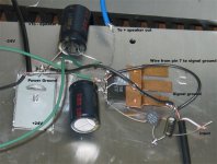
Do I see it correctly that -24V wire is connected to signal ground? Signal ground wire doesn't sem to be connected to pin 7.
Is it aluminum plate everything is resting on?
Did you isolated both grounds and chip case from that plate?
Your input should go to pin 8, which is also connected through 220k resistor with pin 3. Pin 3 is output, pin 7 connected directly to signal ground.
V+ goes to pin 1, V- goes to pin 4. Signal ground and PS capacitors common ground connected together.
Ground to speakers output is taken from common point between caps.
You can go wrong if you do all this.

Hi Magnetmaz,
Maybe it would be helpfull if you could post a list of all the pins and their quensient Voltages. This would force you to measure them again and help us to determine what's wrong. I'm pretty sure we can help you a long way if you post the list.
Regrads,
Thijs
Maybe it would be helpfull if you could post a list of all the pins and their quensient Voltages. This would force you to measure them again and help us to determine what's wrong. I'm pretty sure we can help you a long way if you post the list.
Regrads,
Thijs


I completely rewired up the chip today. Voltages all look good. 36 and -36V from the correct pins to ground.
I even hear a very weak signal coming from the speakers, albeit VERY distorted.
2 questions :
1) Do i have to have an input pot, or resistor to ground? Currently i have my signal hardwired in.
2) My input capacitor is POLAR. I have it wired the correct way, with positive side seeing the input signal.... But could this be my problem? I used all Panasonic FC caps ( all polar ), as suggested by someone on the forum as a cheap alternative to Black Gates.
-Maz
Hi!
Try it without the input cap, I've build GCs with LM3875, LM3876, OPA549 and OPA548, never had to use an input cap (but, I have to admit, my source never changes, as well...)
And I do bend the pins of the ICs, so far it seems that nothing has been broken...
And you can also try putting power and signal ground on one star point... for my GCs seperating them never made a difference... I actually do not really use a star, but a long solid core cable without isolation, directyl soldered to the ground pin of the power connector, something like this:
_________ \ / \ | /
GROUND O-----------------------------
_________ / \ / | \
(Darn! That MessageBoard software erases spaces, just like html...)
Don't give up!
Bye,
Arndt
I think we can really realy help you if you post all exact DC and AC voltages of ALL pins (use input ground as ref, this should be a starground ) , voltage supply points, exact chip type and the exact circuit you are using. This force you to go over this once more to re-re-re-check everything.
- Status
- This old topic is closed. If you want to reopen this topic, contact a moderator using the "Report Post" button.
- Home
- Amplifiers
- Chip Amps
- Help me out, please...