Quite funny, the most important word, the essence of your message indeed, is the word "sometimes". "Sometimes" Elcaps of around 100uF from each supply to ground. What is the definition of "sometimes" ? This, in the context of the Douglas Self NE5532 amp, where each NE5532 is locally decoupled using a small cap between the +V rail and the -V rail, without touching the ground.I do that all the time and it works just fine. I use only one 0.1uF cap and add sometimes Elcaps of around 100uF from each supply to ground. Even very fast chips like the AD797 or the AD8065 worked well done that way.
Last edited:
In the Elektor article they said that the original design contained two electrolytic capacitors that were removed due to "issues". I couldn't work out whether the Elektor team had changed the design, or whether Self did it himself.
In the later article where they tested electrolytics for distortion they came to the same conclusions as Self; they don't cause distortion as long as you make them 'big' enough. But, that being the case, they still didn't say why the original circuit was changed! Did Elektor change it for no good reason, and prove itself guilty of audiophoolery?
The original electrolytics were sharing some PCB tracks with other ground currents. That caused what we all have experienced (knowingly or unknowingly
") ). The ground current through the tracks caused a small voltage that appeared in series with the signal, causing distortion.
). The ground current through the tracks caused a small voltage that appeared in series with the signal, causing distortion. So it's not an issue with the electrolytics, but of PCB routing.
jan didden
Where are the ficken boards, Lebowski ?
http://www.diyaudio.com/forums/atta...g-amp-festival-audio-happening-opyourself.jpg
http://www.diyaudio.com/forums/atta...g-amp-festival-audio-happening-opyourself.jpg
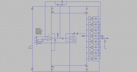
Hi Jan, clear enough, this is why I'm a big fan of inverting power amplifiers, and inverting amplifiers in general. The signal ground path (quiet ground) only connects to the positive input of opamps, very high impedances indeed, no conducted ground current nor radiated ground field. You then get a robust behaviour, stable THD performance less dependent of the connecting environment. See the attached file as example.
By the way, I can't imagine Douglas Self mixing the decoupling ground with the signal ground on the PCB. Which electrolytic capacitors are involved ?
Are you sure the issue was not a class B supply ground current loop radiating at high frequency (say 20 kHz), then inducing a few microvolts into a neighbor track ? Will you investigate ?
Attachments
Last edited:
one difference is striving for efficiency...no waste of materials, labor, cost, energy etc.
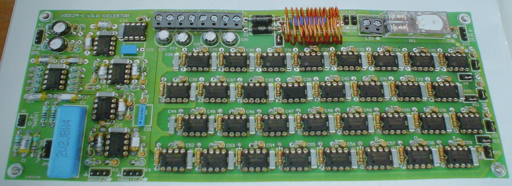
The Self design features:
-high parts count
-high parts cost
-costly and space wasting PCB
-high quiescent power consumption
-low output power
[snip]
Yeah, that's what I told that guy who paid $ 350 for a single 300B
But seriously, I think the parts price of that amp is rather low as the average diy amp goes. It's an interesting exercise to get a very low distortion from down-to-earth parts. Not sexy enough for you I guess...
jan didden
Would you say that if you have local generous decoupling (one 220nF cap per opamp between +V and -V without touching the ground), that there is no real need for electrolytics locally placed between V+ and the ground and between V- and the ground ? This principle looks valid. Of course, you still need big electrolytic caps in the power supply PCB, next to the rectifier.If i use lokal Elcaps depends on the layout. Most of the time i have generous decoupling anyway so do not need the aditional 100uF caps. In case of a shunt regualtor it may be different because low impedance decoupling may make the shunt regulator oscilate.
Now consider the Compact Blameless amplifier.
The Signal Transfer Company: Compact Blameless Power Amplifier
We can see many electrolytic caps over there.
I'm in search of a near 1ppm THD amp, say 25 watt into 8 ohm, having no electrolytics on board, only 220nF caps between the +V and the -V without touching the ground. Do you know such design ? Of course, there are big electrolytic caps in the power supply PCB, next to the rectifier.
Twisting the supply wires between the PSU and the elco-free AMP would cancel the class B electromagnetic radiated field, isn't ?
In this context, there is thus less need for low-pass filtering the audio current flowing into the PSU-to-AMP wires, isn't ?
Better radiate a linear electromagnetic field, closely following the load current, than conveying supply spikes caused by elcos located on the AMP PCB, isn't ?
Elco-free power amps, this looks completely justified, imo. From the above considerations, it should be considered as a sign of quality.
Maybe adding only one elco cap at the PSU input terminals, between V+ and V- without touching the ground ? At the expense of conveying more supply spikes ? It all depends the PSU rejection of the amp. If the PSU is regulated and/or if the amp has a fine PSU rejection I wouldn't add such elco cap at the PSU input terminals.
Last not but least, once you feel happy with a PSU decoupling arangement, is it valid both for a single-ended load and a bridge-tied load ? In a single-ended load, where do you connect the speaker return ?
Last edited:
Not sexy enough
Me think, if i throw a SMPS in front of the LT regulators, i have a nice flat and compact amp for esoteric headphone on back seat, already have sig lighter plug in the back and trunk.
(only requires a recap/rewinding of a switcher module that's rotting away on attic, from Giesberts '94 car-amp project)
Gimme the boards, LeSelfski !!!
(sorry about that, i suffer from Self-induced de la Tourette's)
Would you say that if you have local generous decoupling (one 220nF cap per opamp between +V and -V without touching the ground), that there is no real need for electrolytics locally placed between V+ and the ground and between V- and the ground ? This principle looks valid. Of course, you still need big electrolytic caps in the power supply PCB, next to the rectifier.
Now consider the Compact Blameless amplifier.
The Signal Transfer Company: Compact Blameless Power Amplifier
We can see many electrolytic caps over there.
I'm in search of a near 1ppm THD amp, say 25 watt into 8 ohm, having no electrolytics on board, only 220nF caps between the +V and the -V without touching the ground. Do you know such design ? Of course, there are big electrolytic caps in the power supply PCB, next to the rectifier.
Twisting the supply wires between the PSU and the elco-free AMP would cancel the class B electromagnetic radiated field, isn't ?
In this context, there is thus less need for low-pass filtering the audio current flowing into the PSU-to-AMP wires, isn't ?
Better radiate a linear electromagnetic field, closely following the load current, than conveying supply spikes caused by elcos located on the AMP PCB, isn't ?
If you keep the power leads between regulator and opamp power pins short and use a very low impedance power supply, usually no need for electrolytic caps, so a good film cap between V+ and V- should be sufficient. Resulting in better sound if everything done right.
In this design there are too many opamps to satisfy either of the above - but it may sound good and I guess there is only one way to find it out - to build it and listen.
Last edited:
Say I manage to get an ultracompact blameless parallel amp like the one illustrated above (Kuroda_m) in post #44, using SMT devices and a x86 processor cooler. Elco-free. Only 220nF film caps for each amp (or buffer or quad amp).
Say I connect three different sorts of power supplies :
a) two 18V / 120 watt switchmode laptop power supplies making up + 18V and - 18V
b) one conventional unregulated + 18V and -18V supply using 4 x 4,700µF caps in total
c) one regulated + 18V and -18V supply like the one described in the Elektor-Self NE5532 project
What are the expected perceived quality differences ?
Can you describe ?
Last edited:
Me think, if i throw a SMPS in front of the LT regulators, i have a nice flat and compact amp for esoteric headphone on back seat, already have sig lighter plug in the back and trunk.
(only requires a recap/rewinding of a switcher module that's rotting away on attic, from Giesberts '94 car-amp project)
Gimme the boards, LeSelfski !!!
(sorry about that, i suffer from Self-induced de la Tourette's)
Elektor will supply the boards but I guess they will be offered together with Part 2, next issue.
jan D
Very annoying habit, 2 more weeks of survival training.
On top of +1 month for T minus zero BC. (which leaves the ultimate emergency option of reading the Yaniger article)
Seriously, that compact Bla-me-Less would make a nice car amp, striked the superficial resemblance button of the Elektor Giesberts design somewhatish.
On top of +1 month for T minus zero BC. (which leaves the ultimate emergency option of reading the Yaniger article)
Seriously, that compact Bla-me-Less would make a nice car amp, striked the superficial resemblance button of the Elektor Giesberts design somewhatish.
one difference is striving for efficiency...no waste of materials, labor, cost, energy etc.
The Self design features:
-high parts count
-high parts cost
-costly and space wasting PCB
-high quiescent power consumption
-low output power
it seems like being a nice case study or gimmick for a magazine like Elektor, no complains from me...yet I wouldn't expect it coming from Mr. Self
regards
In a way that summed up most of my feelings on it really... ultimately though Doug is in the game to profit from his designs... and it really is (to me) a very elegant and well thought out design. It's different, and I wouldn't like to pre judge it sonically without having had the chance for a full and detailed audition.
I'm sure Doug is reading this thread too... perhaps we might even elicit some comment
speaker return goes to the main audio star ground.In a single-ended load, where do you connect the speaker return ?
I doubt that. He makes plenty of money as a pro audio EE. I think his published designs come more from an academic desire to publish, to teach and inform, and to stamp out audiophoolery. The money he makes from SignalTransfer must be puny.In a way that summed up most of my feelings on it really... ultimately though Doug is in the game to profit from his designs...
Very annoying habit, 2 more weeks of survival training.
On top of +1 month for T minus zero BC. (which leaves the ultimate emergency option of reading the Yaniger article)
Seriously, that compact Bla-me-Less would make a nice car amp, striked the superficial resemblance button of the Elektor Giesberts design somewhatish.
There's a lot of Giesbert in that realisation
jan didden
How to document the Elektor - Douglas Self NE5532 OpAmplifier listening test sessions ? Read this : ELEKTOR.com
Last edited:
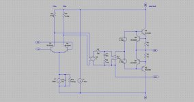
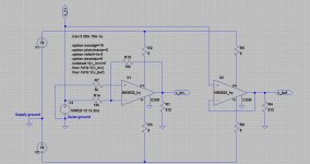
Can somebody check my simulation files and hybrid opamp models ? See attached .zip file. With those models, a NE5532 is not supposed to deliver the 5ppm THD claimed by the Elektor - Douglas Self NE5532 OpAmplifier, for 8 watt at 1 kHz into 8 ohm. According to the simulation, the non-inverting topology used by Self delivers less THD than the inverting topology, which is counter-intuitive. This newest Self design intrigues me.
Attachments
Last edited:

- Status
- This old topic is closed. If you want to reopen this topic, contact a moderator using the "Report Post" button.
- Home
- Amplifiers
- Chip Amps
- Doug Selfs NE5532 Power Amp. Thoughts anyone !