I didn't knew that, why C17, C18, C19 and C20 are not being used and supplied with the kit?
As I've said several and several times:
that caps are NOT part of Mauro Penasa's design (added later by TP), he thinks they disrupt the MyRef 'floating' rails and most important:
it sounds better without...
Mounting chip to heat sink
Just a quick note to ask if there would be a problem using an aluminiumk shim pad between the chip and the heat sink proper?
Even with relatively simple tools (small hacksaw, file, drill) it would be possible to make a shim, I would use a section slightly bigger than the chip, cut from one face of a piece of extruded aluminimum angle, which is pretty flat both sides. Plenty of heat sink compound on both faces.
I can't open Bill P's pictures from post 31 (sadly), but if the chip will mount with the legs bent 'a bit' then 3mm or 1/8" (3.17mm) should give plenty of clearance...
Even half that perhaps...
Thanks everyone for all the good input...
Bill O
Last edited:
Just a quick note to ask if there would be a problem using an aluminiumk shim pad between the chip and the heat sink proper?
Even with relatively simple tools (small hacksaw, file, drill) it would be possible to make a shim, I would use a section slightly bigger than the chip, cut from one face of a piece of extruded aluminimum angle, which is pretty flat both sides. Plenty of heat sink compound on both faces.
I can't open Bill P's pictures from post 31 (sadly), but if the chip will mount with the legs bent 'a bit' then 3mm or 1/8" (3.17mm) should give plenty of clearance...
Even half that perhaps...
Thanks everyone for all the good input...
Bill O
You can use a shim but it adds an extra thermal interface that degrades the heat flow path. To make the degradation small the shim must be very flat with no burrs. Heat sink compound goes on one face, the one that mates to the heatsink. A little compound goes a long way - apply too much and the thermal conduction becomes worse. The shim side facing the LM3886 needs to be electrically insulated. No thermal compound used there - use the insulator in the kit. You really need an insulating shoulder washer so the mounting screw does not short the LM3886 tab to the heatsink. Some people use nylon screws to get around the shorting issue but they are not capable of anywhere near the torque that should be applied in mounting the LM3886. Use a real screw, the right insulators, and check for short circuits with an Ohmmeter when you are done.
Mounting chip to heat sink
Thanks Bill P,
I have to confess I have a couple of insulated LM3886 lined up for this build.
Looking at your very clean build Bill P (I can see the pics now) it looks like an insulated chip might actually have just enough extra thickness?
Has anyone tried it yet?
Still I am sure there are any number of good solutions for this mounting issue.
Bill O
According to the National datasheet for the LM3886 the distance from leads to the back of the chip is 4.29mm for both the T and TF packages.
The heatsink has a hole for mounting the Caddock so the position of the resistor on the heatsink is determined. If you want to raise the whole heatsink off the PC board and support the whole assembly with the resistor leads, I don't recommend that. As it is the assembly is wobbly with the back of the heatsink resting on the board. Once the amp is finalized here I plan to put a bead of glue along the back of the heatsink where it touches the board to stabilize the assembly against vibration.
The heatsink has a hole for mounting the Caddock so the position of the resistor on the heatsink is determined. If you want to raise the whole heatsink off the PC board and support the whole assembly with the resistor leads, I don't recommend that. As it is the assembly is wobbly with the back of the heatsink resting on the board. Once the amp is finalized here I plan to put a bead of glue along the back of the heatsink where it touches the board to stabilize the assembly against vibration.
Unless you drill it. Might be a quick solution. I haven't got the heatsink in my hands yet, though.The heatsink has a hole for mounting the Caddock so the position of the resistor on the heatsink is determined. If you want to raise the whole heatsink off the PC board and support the whole assembly with the resistor leads, I don't recommend that. As it is the assembly is wobbly with the back of the heatsink resting on the board. Once the amp is finalized here I plan to put a bead of glue along the back of the heatsink where it touches the board to stabilize the assembly against vibration.
Unless you drill it. Might be a quick solution. I haven't got the heatsink in my hands yet, though.
The heatsink is made of 1.25mm thick soft aluminum and the greatest care must be used if you drill it yourself. With such thin material it would be easy to ruin the surface flatness. There also must not be a burr left around the newly drilled hole. As with the LM3886, the Caddock resistor needs an interface between it and the heatsink - either a thermal pad or thermal grease.
The position of the existing hole in the heatsink is good enough so I used it to mount the resistor.

Rizla king size rules! or rolls? 
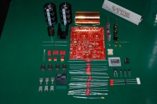
This is the first picture of the kit I see with all the components lied on a table. Now I can see with details all the components I had only in mind. You stolen me this picture! I was thinking in taking it as soon as I receive mine!
Just joking
Those obligattos look impressive in any situation.
Waiting to see your kit assembled...
As I may assume, obligatto's case is isolated from both positive and negative legs. So, will it give any benefit by tiying it to ground? It should act as an EMI shield for all the signal path inside the cap...
Regards,
Regi
My kit has arrived, beautifully packed, thanks Uriah. Just out of curiousity, will a 25W soldering iron be sufficient to ensure good solder joins or would something more powerful be better suited for this board? More components to solder than I realised and lots of copper on those boards!! Thanks, Mark
Rev C hits Japan
My bits arrived in good shape on Monday. Many thanks for all the hard work Uriah (and Sonidas).
The gorgeous Obligatto's are laquered with something so I am not sure how you would make a good conection to the outer case to ground it Regi.
I wanted to polish em up and leave them in view outside the amp case somewhere, but I expect I'll grow up before I actually do it.
Nice to see a pack of king size blue Shark, ah such nostalgia! Not from Camberwell are you?
Bill O
So what's the consensus for the best method to connect/mount the Obbligato's? I was thinking about lengthening the leads on the cap's slightly by soldering a short piece of wire to each leg. Then solder those wires to the board.
Doing so will allow me to place the Cap to the sied of the board where it is supposed to fit, but also allow me to get it as close the edge of the board as possible.
As for mounting, I think I'll epoxy some solid foam/neoprene to the bottom of the case, drill a few holes either side of the foam, and then cable tie the cap to it.
Not ideal in terms of exterior finish, but the only other alternative is to make some form of cradle for it to fit into, perhaps out of MDF. Drill so holes so that cable ties can be passed through it, then expoxy the whole lot to the case, line it with some foam to cushion the cap and then cable tie the cap in place.
Obligatto mounting
Others will chip in about where to mount the caps in relation to other components to minimise noise. I just wanted to suggest silicone sealant, or caulking (or whatever you call it in your area) as a reasonable way to hold down big components.
It is very heat resistant, offers some vibration damping (where it may be appropriate), and the component can still be sliced off with a sharp thin bladed knife later if needed.
Surfaces need to be degreased, then stick it down with a big blob of silicone.
Shoot me down if this is rubbish!
Bill O
Guys I hope to get so answering some questions tomorrow. Going to try to hit the post office today with a shipment. Regi, yours ship tomorrow. Sorry bud.
Baby is here and for that I have been away. Family left today back to Indiana. Trying to catch up with everything. If you have questions earlier in this thread that I might be able to answer maybe throw me a link to the question or restate it. I wont assume you dont know the answer yet.
I mounted my heatsink for Caddock on top. Do it either way I suppose. I used the Caddocks long legs to get it high off of the surface of the board. I would have to remove the sink to get to the LM318. This doesnt bother me but the perfectionist might see it differently.
Please people do not forget your insulation and shoulder washer on your main heastink/LM3886. If you forget either one it will be a short lived life for your amp.
I will be working hard to catch up so give me some slack if I am slow to get back to full steam on the threads.
Uriah
First of all, Uriah, congratulation for your son Hope everything went really well
Using silicone would be the best method and most versatile one.
Hope everything went really wellI think that the method of connecting the obligattos will depend on the case, and the internal disposition of boards and components you are going to do. For not having a tie being seen on the outside you could attach a pair of little L pieces to hold it. I like the foam/neoprene idea, I will do the sameSo what's the consensus for the best method to connect/mount the Obbligato's? I was thinking about lengthening the leads on the cap's slightly by soldering a short piece of wire to each leg. Then solder those wires to the board.
Doing so will allow me to place the Cap to the sied of the board where it is supposed to fit, but also allow me to get it as close the edge of the board as possible.
As for mounting, I think I'll epoxy some solid foam/neoprene to the bottom of the case, drill a few holes either side of the foam, and then cable tie the cap to it.
Not ideal in terms of exterior finish, but the only other alternative is to make some form of cradle for it to fit into, perhaps out of MDF. Drill so holes so that cable ties can be passed through it, then expoxy the whole lot to the case, line it with some foam to cushion the cap and then cable tie the cap in place.
Using silicone would be the best method and most versatile one.
More important than more power is to be temp regulated, and off course having a good bit. Digital or analog control. I have one that shows you the actual iron temp on a display, I use to solder boards at around 270º, the minimum that it solders well.My kit has arrived, beautifully packed, thanks Uriah. Just out of curiousity, will a 25W soldering iron be sufficient to ensure good solder joins or would something more powerful be better suited for this board? More components to solder than I realised and lots of copper on those boards!! Thanks, Mark
- Status
- This old topic is closed. If you want to reopen this topic, contact a moderator using the "Report Post" button.
- Home
- Amplifiers
- Chip Amps
- MyRefC build guide