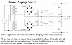
Sir mile please response... my transformer is 22-0-22vAC (+/-30vDC).
what would be the zener diode voltage rating instead of 16v?
I am saying about apex lm3886 gainclone ver:1
Use 10-12v zener
Hi,
I like to Parallel Super Gainclone, like as mentioned in Parallel LM3886 Diagram using wire wound 0.5 ohm 1 watt resistor (3) per channel and ground with 0.1uf (ceramic or film capacitor) with 2 ohm 1/w metal resistor.
Mile, Prasi can you guys just confirm whether it will work or not.
Thanks in Advance,
Nandhakumar
Following the datasheet, a single lm3886 can handle 50W cont. avg. output power into a 8Ohm load with supply voltage +-35V --> I = sqrt(P/R) = sqrt(50/8) = 2,5A
So it needs 2,5A continuous current
and 2,5*sqrt(2) = 3,54A peak current
Multiply those values times 5 and you get what 5 of such boards need
So it needs 2,5A continuous current
and 2,5*sqrt(2) = 3,54A peak current
Multiply those values times 5 and you get what 5 of such boards need
Following the datasheet, a single lm3886 can handle 50W cont. avg. output power into a 8Ohm load with supply voltage +-35V --> I = sqrt(P/R) = sqrt(50/8) = 2,5A
So it needs 2,5A continuous current
and 2,5*sqrt(2) = 3,54A peak current
C'mon! 2 * 35V * 2.5 A = 175 W. At full output power of 50 watts that would equal to 125 watts of thermal dissipation. Never ever!
Best regards!
You're right. That sounds a little bit too much.C'mon! 2 * 35V * 2.5 A = 175 W. At full output power of 50 watts that would equal to 125 watts of thermal dissipation. Never ever!
Best regards!
But whats wrong about my calculation then?
Yes, dissipation always is input DC power minus output power.
Btw, 1.25 A of DC consumption, which is half of the value that you've calculated, seem to be more reasonable: 35 V * 2 * 1.25 = 87.5 W, minus 50 W output = 37.5 W dissipation. Remember that each half wave only draws current from one rail, not from both simultaneously.
Best regards!
Btw, 1.25 A of DC consumption, which is half of the value that you've calculated, seem to be more reasonable: 35 V * 2 * 1.25 = 87.5 W, minus 50 W output = 37.5 W dissipation. Remember that each half wave only draws current from one rail, not from both simultaneously.
Best regards!
Use 10-12v zener
Sir mile i have another question. Actually i am kind of dumb
I didn't mention trafo VA rating. 22-0-22vAC 5amps (220VA).
Do you think 10-12v zener will work properly when fully loaded?
Thnks & no more questions
Have a good day.
Hello Namdhakumar
Please take a look at this page, it's Mick Feuerbacher's 2 resistor 3886
Mick Feuerbacher Audio Projects
The power supply is a bit furher down the page
I'm making it at the moment and got one channel rigged up and laughed out loud when I heard it, fast, analytical, transparent, huge dynamic range
But then I'm just a listener
Cheers
Last edited:
- Home
- Amplifiers
- Chip Amps
- LM3886 Schematics + PCB
