Great Job Nuuk on the site...its refreshing to see someone taking hours of their personal time to help others starting out
Thanks Joe, I can still remember the frustration of starting out and always seeming to have those 'blanks' that I couldn't fill in without a lot of pestering of other people for the information. And do I do believe that you get out of life what you put in!
Great job. Thank you.
I have so much work to do now
I am planning on building five stereo gainclones , active crossovers ( 4th order l-r, I thought about a 100db step but i'm trying to budget), speakers and finish my new turntable. At least I have everything designed on paper. Oh yeah, i have to fit my wife and day job in there also. Damn ambition!
Nice job!
Hey Nuuk,
Excellent job you made there.
Fantastic!
So good I was only able to see a typing error:
"(Please not that this figure is correct where a full rectifier bridge is used). "
You mean "note".
This is what I found, because everything is impressively simple, clear and correct.
Keep the good work, this is what I call public service.
So good I was only able to see a typing error:
Hey Carlos - thank goodness you only saw that one
") I found quite a few with the spell-checker this morning and will put up a corrected version later on.
I found quite a few with the spell-checker this morning and will put up a corrected version later on.Funny thing is, it doesn't matter how many times I read through something I have written, I always manage to miss the mistakes!
 it has been pointed out to me (on the chipamp forum) that I have got the polarity wrong for the decoupling cap attached to pin 4 (-ve supply).
Hi, Nuuk
Your site is very informative, I'd only suggest more pics. However, I think I've found an error in the article "How do I wire up the transformer?".
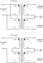
"With dual secondaries (4 wires), two wires will supply the secondary voltage and two wires will supply the zero voltage. You will need to know which wire is which and this information should be supplied with the transformer. The two zero volt wires are joined together and connected to the zero volt rail. The other two wires are connected to the rectifier bridge."
I think the last two sentences should be:
"One secondary wire and one 0 wire are joined together and connected to the zero volt rail. The other secondary wire is connected to one bridge AC input and the other 0 wire is connected to the other bridge AC input."
Regards
Your site is very informative, I'd only suggest more pics. However, I think I've found an error in the article "How do I wire up the transformer?".
"With dual secondaries (4 wires), two wires will supply the secondary voltage and two wires will supply the zero voltage. You will need to know which wire is which and this information should be supplied with the transformer. The two zero volt wires are joined together and connected to the zero volt rail. The other two wires are connected to the rectifier bridge."
I think the last two sentences should be:
"One secondary wire and one 0 wire are joined together and connected to the zero volt rail. The other secondary wire is connected to one bridge AC input and the other 0 wire is connected to the other bridge AC input."
Regards
Attachments
"One secondary wire and one 0 wire are joined together and connected to the zero volt rail. The other secondary wire is connected to one bridge AC input and the other 0 wire is connected to the other bridge AC input."
Thanks Moamps, I got myself confused there! I'll make the changes to the site. Would it be OK to grab that circuit diagram - I'm getting rather bogged down doing all the graphics and I have a second GC to build for myself!
I'm including a contributor's list at the bottom of the FAQ page. If you would like to be included, let me know your real name.
Nuuk said:
Would it be OK to grab that circuit diagram - I'm getting rather bogged down doing all the graphics and I have a second GC to build for myself!
Hi,
"Just do it",
and.........PCB=printed circuit board

Regards
good work, im also making a website about my gainclone, half for my own reference (always losing circuit diagrams) and half for others. it can be found at: http://www.freewebs.com/matttcatttweb
Nuuk said:
I have a second GC to build for myself!
Me too.
It's done, I only need the transformer.
It's been playing with my bech PSU.
This time it's with LM3886.
samples
Matttcattt, the page is fine.
But if I were you I wouldn't make publicity to the fact you get your chips free from Texas Instruments.
I would take that sentence out of the page.
This applies to everyone.
We should not say to everyone we get samples.
One day they might stop the samples program.
Texas and others.
Let's keep it with us.
And we should not abbuse.
Ok?
Samples
I've often thought about this.
A while back, I got an email from a Texas employee who'd seen my preamp project. I wrote back, explaining how I was slightly ashamed because I'd got my PGA2310's as samples (from Texas, of course). But his position was really good - they had no problem with supplying samples, especially when their products got such a good write-up (his words, not mine!)
I suppose when you think about it, the preamp project on my site is just a big advert for BB/TI
Cheers,
Mark
just because they're free
Yes, but that's different.
Matttcattt says in his page:
"I chose to make this amplifier due to its simplicity (only 7 components per channel and a simple unregulated power supply) and price, as I got the amplifier chips free as samples from Texas Instruments."
And that's the problem.
One of the reasons is price, as he got the chips free from Texas.
It's not saying these are excellent chips.
It's saying they're free and that's why he has chosen them.
I thing this is not saying these Burr-Brown chips are the best or that they are very good.
Matttcattt, you could review this sentence.
I agree
Carlosfm,
I do agree with you about the wording of MatttCattt's page - I was just providing an alternative viewpoint. I don't think they'll stop giving away samples just because a few of us are using them for hobby use, but you're right - we shouldn't abuse the system. I got some LM3875's as samples for my GainClone experiments - I fully intend to purchase some from Farnell for the final construction.
Cheers,
Mark
Re: I agree
You may read post #18 here:
http://www.diyaudio.com/forums/show...507&perpage=15&highlight=samples&pagenumber=2
Impressive, huh?
Some companies should get a nobel prize.
It's not that there are a few of us.
It's that some people call friends to help, and request hundreds of chips in one single day.
So I was giving an advice for everyone of us, the diyers.
Don't spread the word too much.
Matttcattt, you're a nice guy.
Would you change that sentence?
Plllllllleeeeeeeeeeeeeeeeease...
Oh, and I whant to see that car amp!
mhennessy said:Carlosfm,
I do agree with you about the wording of MatttCattt's page - I was just providing an alternative viewpoint. I don't think they'll stop giving away samples just because a few of us are using them for hobby use, but you're right - we shouldn't abuse the system. I got some LM3875's as samples for my GainClone experiments - I fully intend to purchase some from Farnell for the final construction.
Cheers,
Mark
You may read post #18 here:
http://www.diyaudio.com/forums/show...507&perpage=15&highlight=samples&pagenumber=2
Impressive, huh?
Some companies should get a nobel prize.
It's not that there are a few of us.
It's that some people call friends to help, and request hundreds of chips in one single day.
So I was giving an advice for everyone of us, the diyers.
Don't spread the word too much.
Matttcattt, you're a nice guy.
Would you change that sentence?
Plllllllleeeeeeeeeeeeeeeeease...
Oh, and I whant to see that car amp!
I'm confused. I am looking at Daniels' GainKlone on Cattles' website http://www.freewebs.com/matttcatttweb/ and then looking at Nuuk's page. The circuits differ sligthly? On Cattles' page it has the Input capacitor and resistor pointed to pin 8 yet on Nuuk's page it is pointed to pin 7. Which is the right one?
Also what is so special about the separate star grounds? Can I just use a single star ground?
Also what is so special about the separate star grounds? Can I just use a single star ground?
- Status
- This old topic is closed. If you want to reopen this topic, contact a moderator using the "Report Post" button.
- Home
- Amplifiers
- Chip Amps
- Beginner's Gainclone guide